Method for installing anti-pull part

An installation method and technology of the body, which are applied in the directions of building components, earthquake resistance, building types, etc., can solve the problems of poor structural stability of light steel buildings, poor seismic capacity of light steel buildings, and poor deformation resistance of pull-out parts, and are not easy to overturn. , good stability, improve the effect of anti-deformation ability

Pending Publication Date: 2019-09-13
厦门大禾速建建筑科技有限公司
View PDF7 Cites 0 Cited by
  • Summary
  • Abstract
  • Description
  • Claims
  • Application Information

AI Technical Summary

Problems solved by technology

[0003] Most of the existing pull-out parts are L-shaped plates. When installing, the bottom and the foundation or floor truss are tightly fixed together. When the wall or floor truss is subjected to a large pull-out force, this installation method The anti-seismic ability of the light steel buildin

Method used


Image

  • Method for installing anti-pull part
  • Method for installing anti-pull part
  • Method for installing anti-pull part

Examples


Embodiment 1

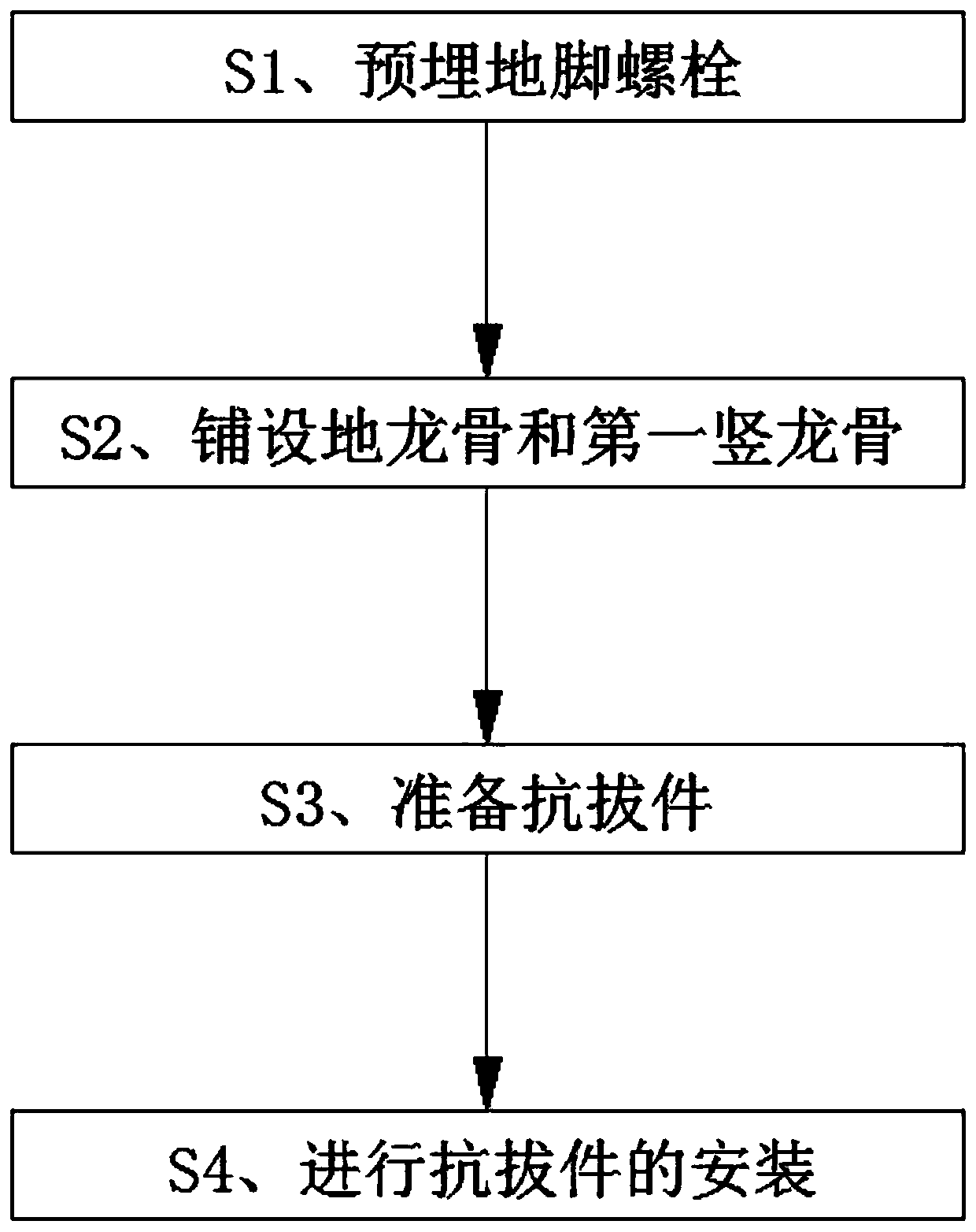
[0064] Cooperate figure 1 , Figure 3 to Figure 7 As shown, the invention discloses a method for installing an anti-pull part, comprising the following steps:

[0065] S1. Pre-bury the anchor bolts 400, pour concrete to form the foundation 200, and expose the anchor bolts 400 to the foundation 200.

[0066] S2. Lay the ground keel 310 , and the ground keel 310 is fixed on the foundation 200 through the expansion bolt 500 .

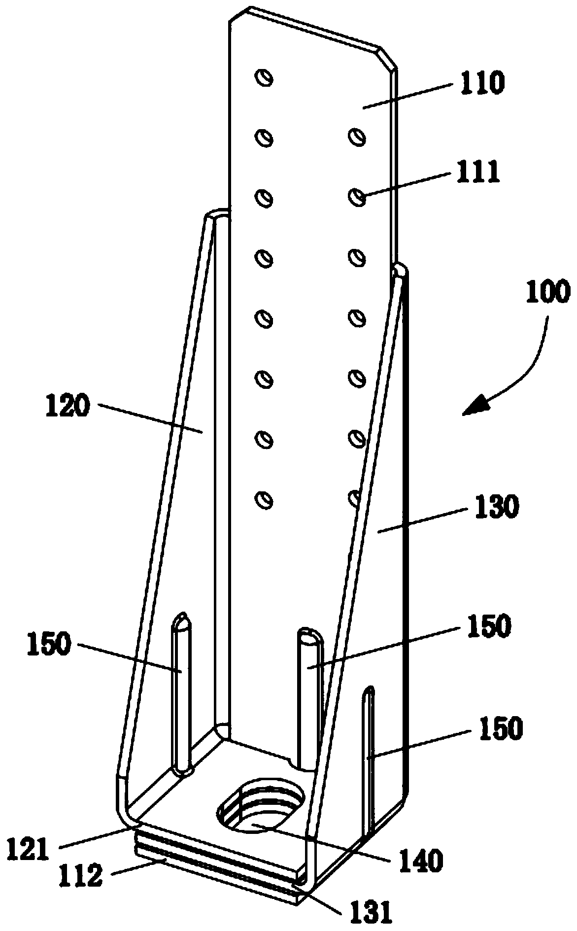
[0067] S3. Lay the first vertical keel 320 in the direction perpendicular to the ground keel 310, so that the first vertical keel 320 is located near the anchor bolt 400, and then prepare the anti-pull piece 100, and both the ground keel 310 and the first vertical keel 320 are used The C-shaped keel or the U-shaped keel fixes the first connecting body 110 of the anti-pull member 100 to the back of the first vertical keel 320, so that the second connecting body 120 and the third connecting body 130 respectively lean against the first vertical keel 320 si...

Embodiment 2

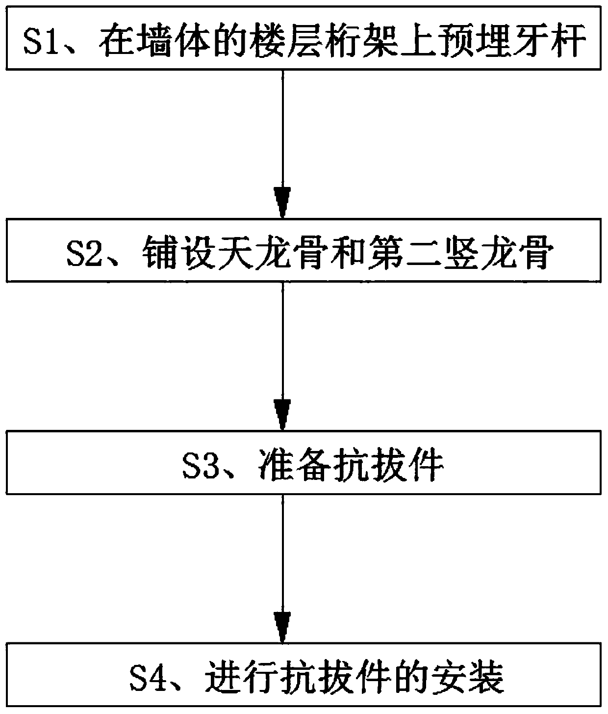
[0082] Cooperate Figure 2 to Figure 6 , Figure 8 and Figure 9 As shown, the invention discloses a method for installing an anti-pull part, comprising the following steps:

[0083] S1. Pre-embed the tooth bar 800 on the floor truss 710 of the wall, and expose the tooth bar 800 to the floor truss 710 . The tooth bar 800 is located in the middle of the floor truss 710 .

[0084] S2. Lay the sky keel 720 at the upper and lower ends of the floor truss 710 of the wall, and lay the second vertical keel 730 in the direction perpendicular to the sky keel 720, and make the second vertical keel 730 close to the tooth bar 800, and the sky keel 720 and the second vertical keel 730 are all C-shaped keels or U-shaped keels, so that the first connecting body 110 of the pull-out member 100 is fixed to the back of the second vertical keel 730, so that the second connecting body 120 and the third connecting body 130 are against the two sides of the second vertical keel 730 respectively.

...


PUM


Abstract

The invention discloses a method for installing an anti-pull part. The method comprises the following steps that S1, anchor bolts are embedded, concrete is poured to form a foundation; S2 a ground keel is paved, the ground keel is fixed on the foundation by expansion bolts; S3, a first vertical keel is paved in the direction perpendicular to the ground keel, and then the anti-pull part is prepared; S4, the anti-pull part is installed, specifically, S41, the anchor bolts are enabled to penetrate through bolt holes of the anti-pull part, and the height between the bottom of the anti-pull part and the top of the foundation is enabled to be H1; S42, the height H1 of the anti-pull part is maintained, and a first connecting body is enabled to be fixed on the first vertical keel by a self-drilling screw; and S43, the anti-pull part is locked and limited. The method enables a light steel building structure to have good earthquake resistance, meanwhile, a buffering part improves the anti-deformation ability of the anti-pull part after installation, and under the action of larger pulling force, a wall body is not prone to being overturned, and floors are not prone to being separated from oneanother, and the stability of a building structure is good.

Description

technical field [0001] The invention relates to the technical field of building connectors, in particular to a method for installing an anti-pullout member. Background technique [0002] Light steel building structure is a building form with thin-walled steel components as the main structure. It is widely used in low-rise buildings because of its light material, easy modular assembly, and environmental protection. In the existing light steel building In the structure, anti-lift parts are installed between the foundation and the wall keel, between the floor truss and the wall keel, to prevent the light steel building structure from overturning under the action of the wind (or even stand up in severe cases) or prevent Detachment between floors. [0003] Most of the existing pull-out parts are L-shaped plates. When installing, the bottom and the foundation or floor truss are tightly fixed together. When the wall or floor truss is subjected to a large pull-out force, this insta...

Claims


Application Information

Patent Timeline
IPC IPC(8): E04B1/38E04B1/98E04H9/02
CPCE04B1/38E04H9/021
Inventor 何永康刘志文那洪志
Owner 厦门大禾速建建筑科技有限公司
Why Eureka
Try Eureka