A low-voltage power distribution cabinet with automatic dehumidification function

A power distribution cabinet and function technology, applied in the substation/distribution device shell, electric components, electromechanical devices, etc., can solve the problems of equipment and personnel injury, general dehumidification effect, uneven heating of power distribution cabinet, etc., to avoid equipment high temperature The effect of aging, accelerating dehumidification speed, and improving dehumidification effect

Active Publication Date: 2020-12-22
WUHAN XIGAO ELECTRICAL APPLIANCE
View PDF6 Cites 2 Cited by
  • Summary
  • Abstract
  • Description
  • Claims
  • Application Information

AI Technical Summary

Problems solved by technology

[0002] The power distribution cabinet is an important part of the power distribution system. Due to factors such as weather and environment, the power distribution cabinet located outdoors often has a lot of water vapor inside, which is easy to form condensation on the electrical equipment, affecting the operation of the electrical equipment, and even causing safety hazards. Hidden danger, the existing power distribution cabinet dehumidification mainly adopts the method of air circulation or installing a heater. The position of the traditional heater is fixed, and it is easy to cause the surrounding equipment to age due to high temperature after long-term work, and the heater leaks, which is easy to damage the equipment and personnel. cause damage, uneven heating in the power distribution cabinet, and general dehumidification effect, a dehumidification device for power distribution cabinet clarified in the present invention

Method used


Image

  • A low-voltage power distribution cabinet with automatic dehumidification function
  • A low-voltage power distribution cabinet with automatic dehumidification function
  • A low-voltage power distribution cabinet with automatic dehumidification function

Examples


Embodiment Construction

[0020] Combine below Figure 1-Figure 7 The present invention is described in detail, and for convenience of description, the orientations mentioned below are now stipulated as follows: figure 1 The up, down, left, right, front and back directions of the projection relationship itself are the same.

[0021] The present invention relates to a low-voltage power distribution cabinet with automatic dehumidification function, which is mainly used in the dehumidification work of the power distribution cabinet. The present invention will be further described below in conjunction with the drawings of the present invention:

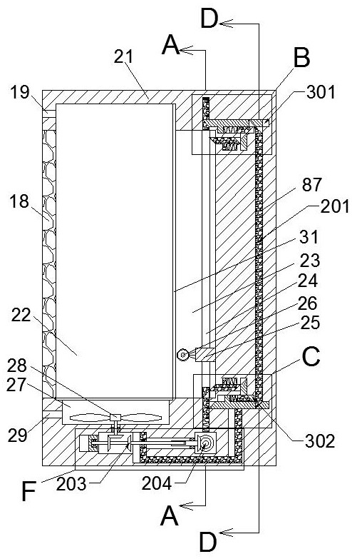
[0022]A low-voltage power distribution cabinet with an automatic dehumidification function according to the present invention includes a cabinet body 21, and a power distribution cavity 22 is arranged on the left end of the cabinet body 21, and the power distribution cavity 22 can be used to place power equipment , the left end of the power distribution chamber 2...


PUM


Abstract

The invention discloses a low-voltage power distribution cabinet with an automatic dehumidification function. The low-voltage power distribution cabinet comprises a cabinet body, wherein a power distribution cavity is arranged in the left end wall of the cabinet body, power equipment can be placed in the power distribution cavity, the left end of the power distribution cavity communicates with theoutside through an exhaust port, a cabinet door is arranged on the lower side of the exhaust port, a main sliding cavity is arranged at the right side of the power distribution cavity, and two lifting lead screws are arranged in the main sliding cavity in the front-back direction. The power distribution cabinet is dehumidified by utilizing a mode of electrically heating air in the cabinet, and afan is arranged to help ventilation of the air in the cabinet so as to improve the dehumidification effect and accelerate the dehumidification speed, the heater is driven by the device to reciprocateup and down, so that the air in the cabinet body is uniformly heated, and high-temperature aging of the device caused by long-time high-temperature baking of the internal electrical device is avoided.

Description

technical field [0001] The invention relates to the technical field of electrical equipment, in particular to a low-voltage power distribution cabinet with an automatic dehumidification function. Background technique [0002] The power distribution cabinet is an important part of the power distribution system. Due to factors such as weather and environment, the power distribution cabinet located outdoors often has a lot of water vapor inside, which is easy to form condensation on the electrical equipment, affecting the operation of the electrical equipment, and even causing safety hazards. Hidden danger, the existing power distribution cabinet dehumidification mainly adopts the method of air circulation or installing a heater. The position of the traditional heater is fixed, and it is easy to cause the surrounding equipment to age due to high temperature after long-term work, and the heater leaks, which is easy to damage the equipment and personnel. Cause damage, uneven heat...

Claims


Application Information

Patent Timeline
Patent Type & Authority Patents(China)
IPC IPC(8): H02B1/56H02B1/30H02B1/28H02K7/116
CPCH02B1/28H02B1/30H02B1/565H02K7/116
Inventor 周雄胡金霞
Owner WUHAN XIGAO ELECTRICAL APPLIANCE
Why Eureka
Try Eureka