
vibration motor

A vibration motor and mover technology, applied in the field of motors, can solve problems such as difficulty and low resonance frequency, and achieve the effect of low resonance frequency and low elastic stiffness

Active Publication Date: 2021-08-10
AAC TECH PTE LTD
View PDF10 Cites 0 Cited by
  • Summary
  • Abstract
  • Description
  • Claims
  • Application Information

AI Technical Summary

Problems solved by technology

It is difficult to simultaneously achieve a low resonance frequency f0, the stiffness of the supporting vibrator and good reliability at large strokes

Method used


Image

  • vibration motor
  • vibration motor
  • vibration motor

Examples


Embodiment Construction

[0022] The present invention will be further described below in conjunction with the accompanying drawings and embodiments.

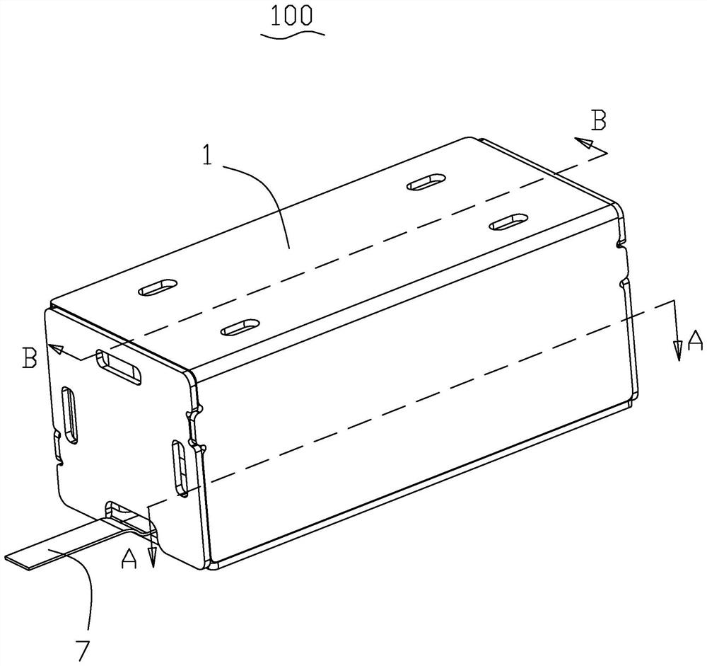
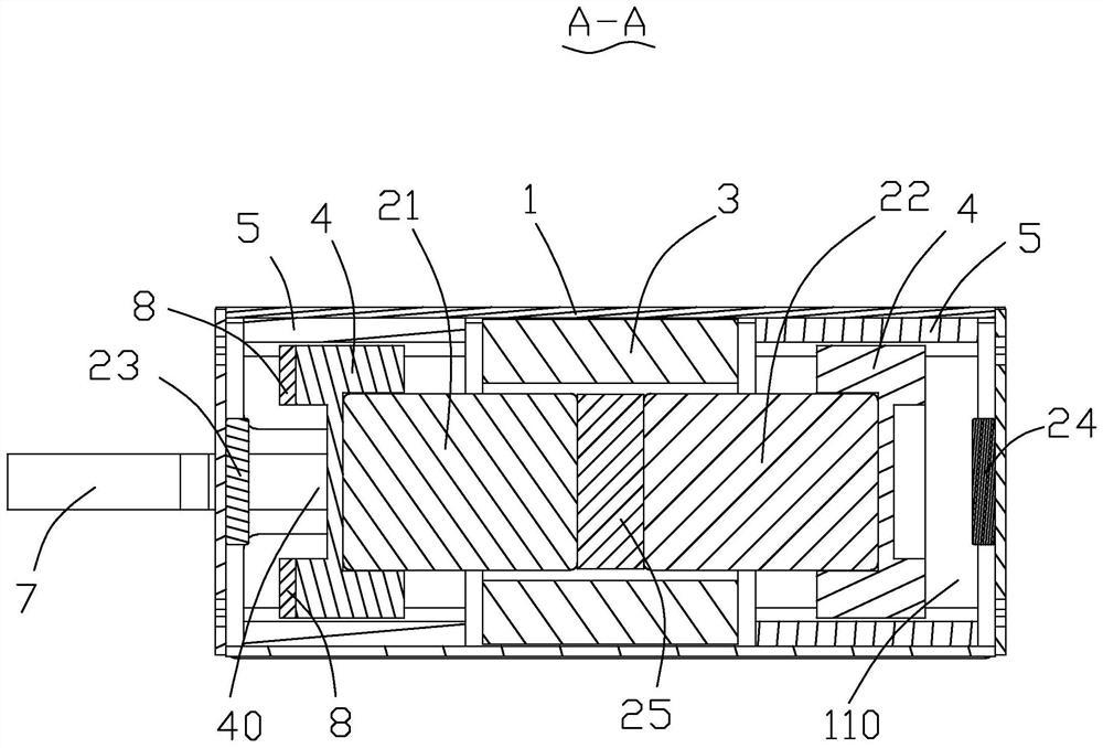
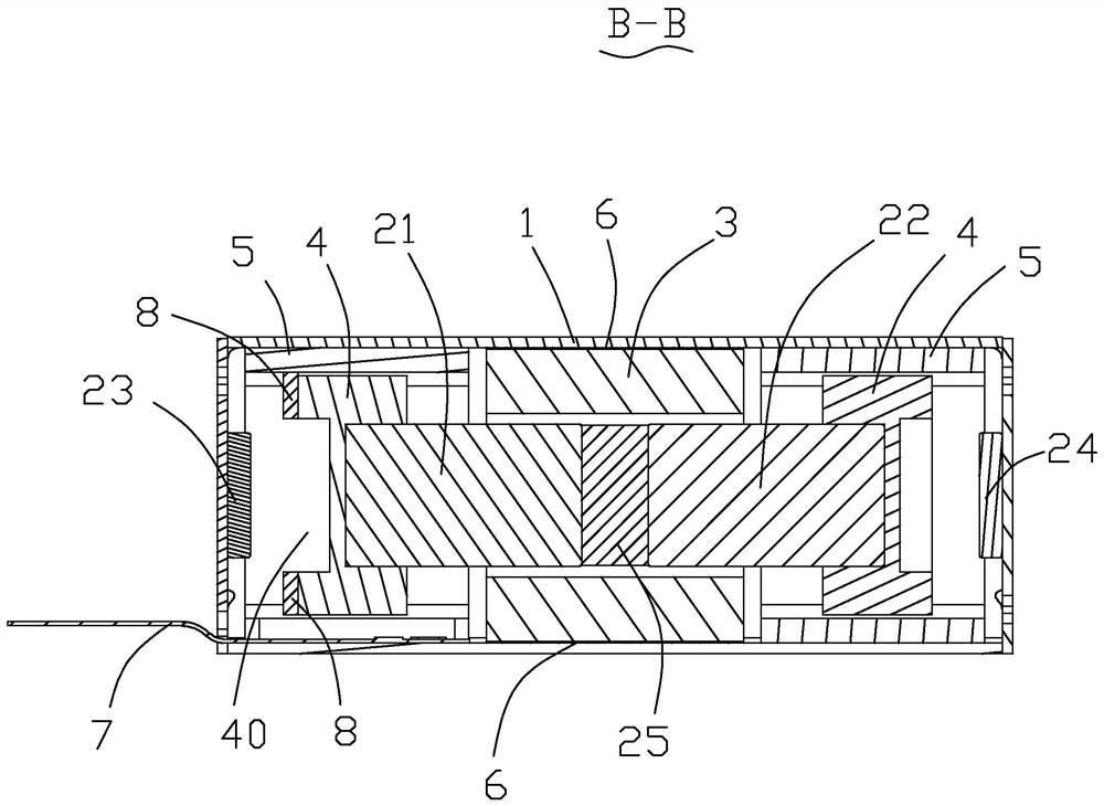
[0023] Please refer to Figure 1-Figure 4 , the present invention provides a vibrating motor 100, comprising a casing 1, a stator installed in the casing 1 and a mover that can move relative to the stator, the mover includes a first magnet 21 and a second magnet 21 arranged side by side along the moving direction Two magnetic steels 22, the stator includes coils 3 wound outside the adjacent two ends of the first magnetic steel 21 and the second magnetic steel 22, and the vibration motor 100 also includes two opposite inner wall surfaces installed on the shell 1 and respectively connected to The opposite ends of the first magnet 21 and the second magnet 22 are opposite to each other and the third magnet 23 and the fourth magnet 24 are arranged at intervals.

[0024] The first magnet 21 and the second magnet 22 adopt symmetrical repelling magnets. The ma...


PUM


Abstract

The present invention provides a vibrating motor, which comprises a casing, a stator installed in the casing, and a mover capable of moving relative to the stator. The mover includes a first magnet and a second magnet arranged side by side along the moving direction of the mover. The stator includes coils wound outside the adjacent two ends of the first magnet and the second magnet, and the vibration motor also includes coils that are respectively installed on the opposite inner walls of the casing and connected to the first magnet and the second magnet respectively. The third magnet and the fourth magnet are arranged opposite to each other and spaced apart. The third magnet and the fourth magnet provide elastic restoring force for reciprocating motion of the mover. When the coil is energized, the first magnet and the second magnet move along the axial direction of the coil, and rebound after hitting the third magnet or the fourth magnet, forming a back-and-forth impact movement, because the third magnet or the fourth The magnetic steel can be made very thin, the elastic stiffness is small, and a low resonance frequency f0 can be realized.

Description

【Technical field】 [0001] The invention relates to the field of motors, in particular to vibration motors. 【Background technique】 [0002] The tactile feedback vibration motor of the game handle in the prior art uses a mechanical shrapnel structure as an elastic and supporting component. The existing mechanical shrapnel structure needs to obtain a low resonance frequency f0, and to achieve a large vibration amount, the vibration displacement must be large. The mechanical shrapnel structure is in There are reliability problems under large displacement. It is difficult to simultaneously achieve a lower resonance frequency f0, the stiffness of the supporting vibrator and good reliability under a large stroke. [0003] Therefore, it is necessary to provide a method to achieve a lower resonance frequency f0, the stiffness of the supporting vibrator and good reliability under a large stroke. 【Content of invention】 [0004] The purpose of the present invention is to provide a vi...

Claims


Application Information

Patent Timeline
Patent Type & Authority Patents(China)
IPC IPC(8): H02K33/10H02K1/34
CPCH02K1/34H02K33/10
Inventor 李刚陈凯吴瑶
Owner AAC TECH PTE LTD
Learn More