
Device for pressing the yarn onto the bobbin

A bobbin and yarn technology, applied in the direction of transportation and packaging, bearings for rotational motion, rigid supports for bearing components, etc., can solve problems such as unfavorable stability of bobbin mandrels, different, uneven loads, etc.

Active Publication Date: 2016-06-29
OERLIKON TEXTILE GMBH & CO KG
View PDF7 Cites 0 Cited by
  • Summary
  • Abstract
  • Description
  • Claims
  • Application Information

AI Technical Summary

Problems solved by technology

However, due to the high and variable tilting stiffness of the rubber elements, this tilted positioning of the central axis leads to very uneven loading of the running tracks of the multi-row bearings
Furthermore, the known O-rings are not suitable for securing the press roller axially with respect to the roller support, i.e. parallel to the axis of rotation of the press roller, so that in the known device the press roller has to be positioned between the rollers in order to press the yarn. Mount at least one fixed bearing on the bracket
The disadvantage of this is that there is a rigid connection between the pressure roller and the roller support at least in the axial direction of the pressure roller, so that the stiffness of the rubber elements on both sides of the pressure roller can be very different, which is very different for the bobbin mandrel. has a very negative effect on the stability of the bobbin and contributes to the sub-harmonic self-excited rotation of the bobbin mandrel

Method used


Image

  • Device for pressing the yarn onto the bobbin
  • Device for pressing the yarn onto the bobbin
  • Device for pressing the yarn onto the bobbin

Examples


Embodiment Construction

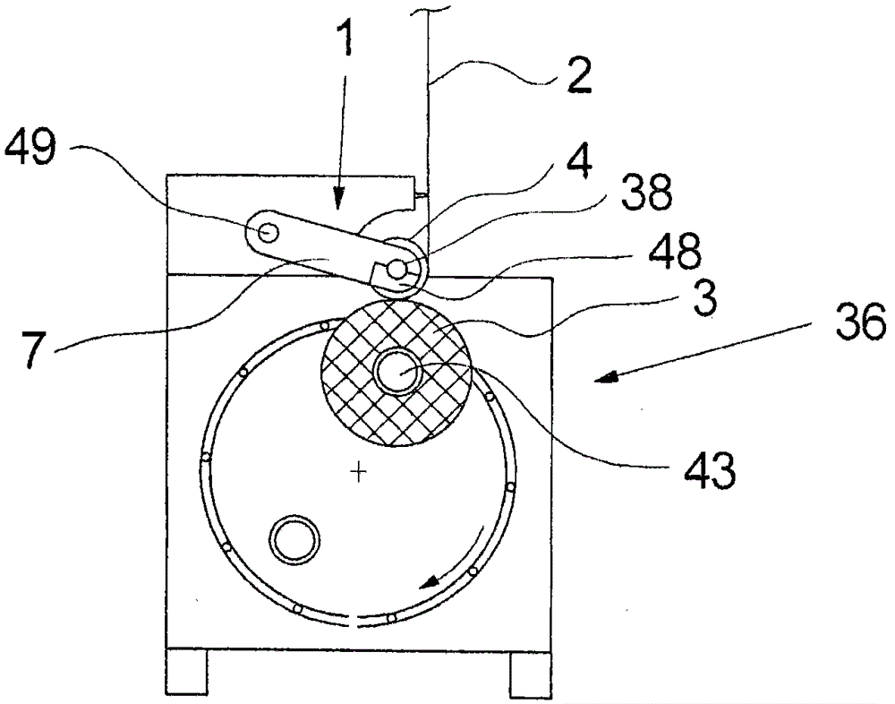
[0024] figure 1 Shown is a winder 36 with a device 1 for pressing the yarn 2 onto the bobbin 3 . The device 1 comprises a pressure roller 4 connected to a winder 36 by means of a movable roller support 7 . The roller carrier 7 is designed as a rocker arm which is held on the winder 36 via a pivot bearing 49 . The press roller 4 is held at the free end of the roller bracket 7 . The pressing roller 4 presses the yarn 2 onto the surface of the bobbin 3 , which is rotatably mounted on the bobbin mandrel 43 .

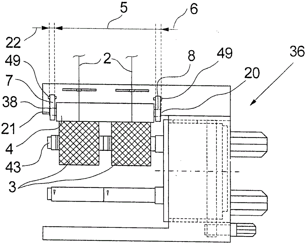
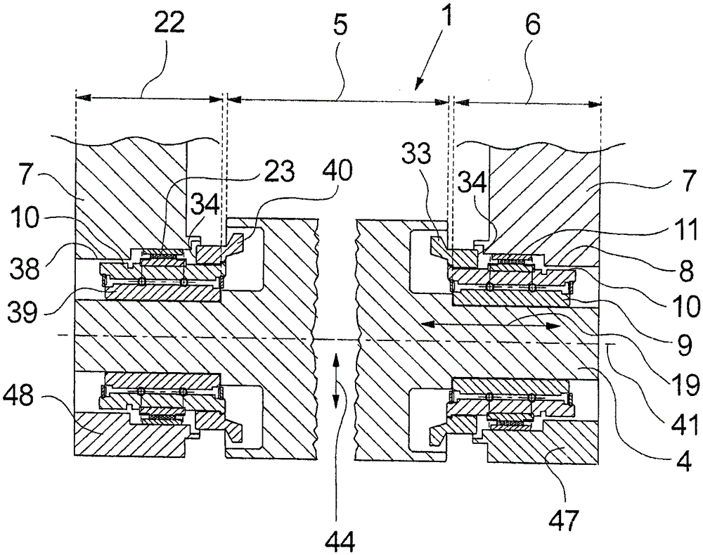
[0025] figure 2 show figure 1 Side view of the winder 36. It can be seen that the pressure roller 4 has a yarn guide 5, in which two yarns 2 are each wound onto a bobbin 3. Furthermore, the pressure roller 4 comprises a first bearing part 6 at the first end 20 which is mounted in a first receptacle 8 of the roller holder 7 . Furthermore, the pressure roller 4 comprises a second bearing part 22 at the second end 21 which is mounted in a second receptacle 38 of the rol...


PUM

PropertyMeasurementUnit
Radial stiffnessaaaaaaaaaa
Lengthaaaaaaaaaa

Abstract

The present invention relates to a device (1) for pressing a thread (2) onto a spool (3), having a pressure roller (4) with a thread guide portion (5) and at least one bearing portion (6, 22), and a roller support (7) with at least one receptacle (8, 38), wherein the pressure roller (4) has a bearing (9, 39) with an outer surface (10) in the region of the at least one bearing portion (6, 22), wherein at least one spring absorber element (11, 23) is arranged on the outer surface (10) of the bearing (9), wherein the pressure roller (4) can be rotated with the bearing (9) and the at least one spring absorber element (11, 23) in which at least one receptacle (8, 38) of the roller support (7) is mounted and wherein the at least one spring absorber element (11, 23) is designed to fasten the pressure roller (4) radially and axially relative to the roller support (7). The present invention also relates to a corresponding winding machine (36). The invention is characterised by an especially effective shock absorption of the pressure roller (4).

Description

technical field [0001] The invention relates to a device for pressing a yarn onto a bobbin. Furthermore, the invention relates to a winding machine with the device according to the invention. The invention is particularly suitable for the production of synthetic yarns. Background technique [0002] From DE 19632748 A1 a winder with pressure rollers mounted on movable roller supports is known. When winding the yarn, the pressure rollers bear against the surface of the bobbin clamped on the driven mandrel and guide the yarn to deposit it on the surface of the bobbin. At the same time, the rotational speed of the press rollers is used to control the drive of the mandrel, so as to obtain a constant peripheral speed of the bobbin that continues to grow. In order to obtain a uniform bobbin structure, pressure rollers are held on the surface of the bobbin with a predetermined pressing force. In order to reduce the vibration generated by the driving mandrel, the bearing of the p...

Claims


Application Information

Patent Timeline
IPC IPC(8): F16F1/38F16C27/06F16C13/02B65H54/52
CPCB65H54/52B65H2701/3132F16C13/06F16C27/066F16C35/077F16C2202/08
Inventor H·瓦尔特曼J·科瓦尔斯基M·埃伯特
Owner OERLIKON TEXTILE GMBH & CO KG
Learn More