
Vehicle data recorder with bridging type heat dissipation structure

A technology of driving recorder and heat dissipation structure, which is applied in the direction of registration/indication of vehicle operation, instruments, registration/indication, etc., which can solve problems such as heat cannot be dissipated, and electronic products cannot be used normally due to high temperature, so as to improve heat dissipation efficiency Effect

Pending Publication Date: 2019-09-13
SHENZHEN ZUSHIHUI TECH CO LTD
View PDF0 Cites 0 Cited by
  • Summary
  • Abstract
  • Description
  • Claims
  • Application Information

AI Technical Summary

Problems solved by technology

[0003] At present, a layer of heat dissipation layer is generally attached to the electronic product components that generate heat. Generally, the heat dissipation layer is composed of metal aluminum or metal aluminum plus graphene sheet. The heat dissipation layer is still inside the entire driving recorder. After the heat is dissipated from the heat sink, the heat It is still inside the electronic product, which can only be exported by air, but the space is narrow and the air circulation is not enough, so the heat cannot be dissipated, and the temperature of the electronic product is too high to be used normally. Therefore, we propose a driving recorder with a bridge heat dissipation structure

Method used


Image

  • Vehicle data recorder with bridging type heat dissipation structure
  • Vehicle data recorder with bridging type heat dissipation structure
  • Vehicle data recorder with bridging type heat dissipation structure

Examples


Embodiment Construction

[0018] The following will clearly and completely describe the technical solutions in the embodiments of the present invention with reference to the accompanying drawings in the embodiments of the present invention. Obviously, the described embodiments are only some, not all, embodiments of the present invention. Based on the embodiments of the present invention, all other embodiments obtained by persons of ordinary skill in the art without making creative efforts belong to the protection scope of the present invention.

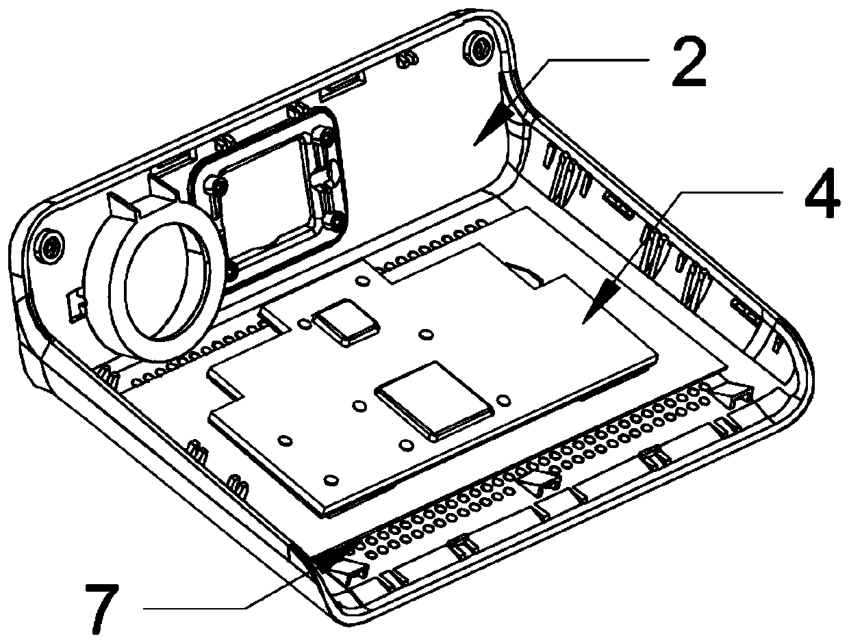
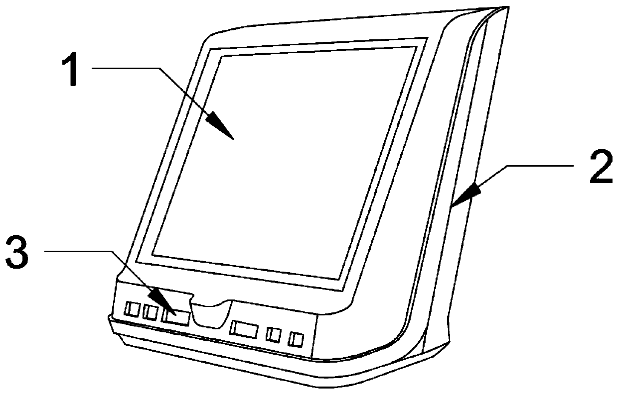
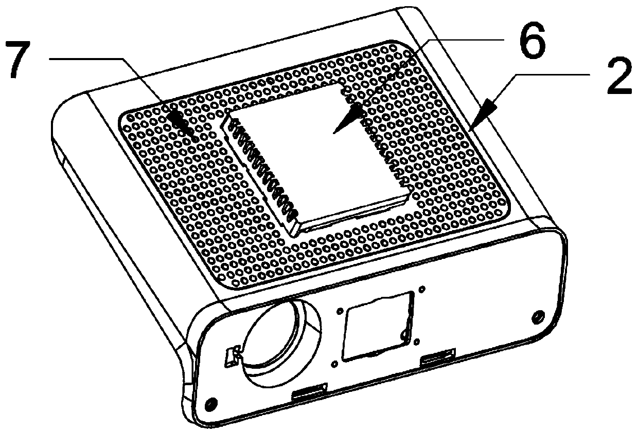
[0019] see Figure 1-5 , the present invention provides a technical solution: a traffic recorder with a bridge-type heat dissipation structure, including an instrument body 1, a back shell 2, a front heat dissipation hole 3, an inner heat dissipation plate 4, a rear heat dissipation hole 7, a silica gel heat conduction plate 8 and The outer cooling plate 9, the back shell 2 is fixed on the back of the instrument body 1, the front bottom of the instrument body ...


PUM


Abstract

The invention discloses a vehicle data recorder with a bridging type heat dissipation structure. The vehicle data recorder comprises a recorder body, a back shell, front heat dissipation holes, an inner heat dissipation plate, rear heat dissipation holes, silica gel heat conduction plates and an outer heat dissipation plate. The back shell is matchingly fixed with the back surface of the recorderbody, the bottom end of the front surface of the recorder body is provided with the front heat dissipation holes, the rear heat dissipation holes are uniformly arranged at the surface of the back shell, the outer heat dissipation plate is fixed at the inner surface of the internal portion of the back shell, the inner heat dissipation plate is pasted at the surface of the internal appliance elementof the recorder body, the silica gel heat conduction plates are symmetrically arranged between the inner heat dissipation plate and the outer heat dissipation plate, and the inner heat dissipation plate and the outer heat dissipation plate are spliced through the silica gel heat conduction plates. The vehicle data recorder adopts two small silica gel heat conduction plates to connect the inner heat dissipation plate and the outer heat dissipation plate, the outer heat dissipation plate is directly attached to the rear heat dissipation holes of the back shell to greatly improve the heat dissipation effect of the device, and the design of the H bridge saves the space and is cooperated with the arrangement of the front heat dissipation holes and the rear heat dissipation holes to improve theinternal air convection and increase the heat extraction effect.

Description

technical field [0001] The invention relates to the technical field of driving recorders, in particular to a driving recorder with a bridging heat dissipation structure. Background technique [0002] In order to improve driving safety, the driving recorder is a necessary equipment for vehicles, but the current driving recorder has defects. The driving recorder is in the car, and the weather is hot. The travel recorder is generally installed on the front windshield, and the operating environment temperature is relatively high. , and electronic products will generate a lot of heat after long-term use, which will make the temperature of the entire electronic product relatively high. [0003] At present, a layer of heat dissipation layer is generally attached to the electronic product components that generate heat. Generally, the heat dissipation layer is composed of metal aluminum or metal aluminum plus graphene sheet. The heat dissipation layer is still inside the entire drivi...

Claims


Application Information

Patent Timeline
IPC IPC(8): H05K7/20G07C5/08
CPCH05K7/20436G07C5/08
Inventor 林军
Owner SHENZHEN ZUSHIHUI TECH CO LTD
Learn More