Disinfection cabinet

A technology of disinfection cabinet and inner tank, applied in the field of disinfection cabinet, can solve the problems of ineffective volatilization, rot and mildew of the cabinet, etc., and achieves the effect of convenient operation and avoiding leakage

Active Publication Date: 2019-09-17
NINGBO FOTILE KITCHEN WARE CO LTD
View PDF17 Cites 2 Cited by
  • Summary
  • Abstract
  • Description
  • Claims
  • Application Information

AI Technical Summary

Problems solved by technology

In this way, the water vapor will gather inside the cabinet and cannot be effectively volatilized. After long-term use, it will easily cause the cabinet to rot and mildew

Method used


Image

  • Disinfection cabinet
  • Disinfection cabinet
  • Disinfection cabinet

Examples


Embodiment 1

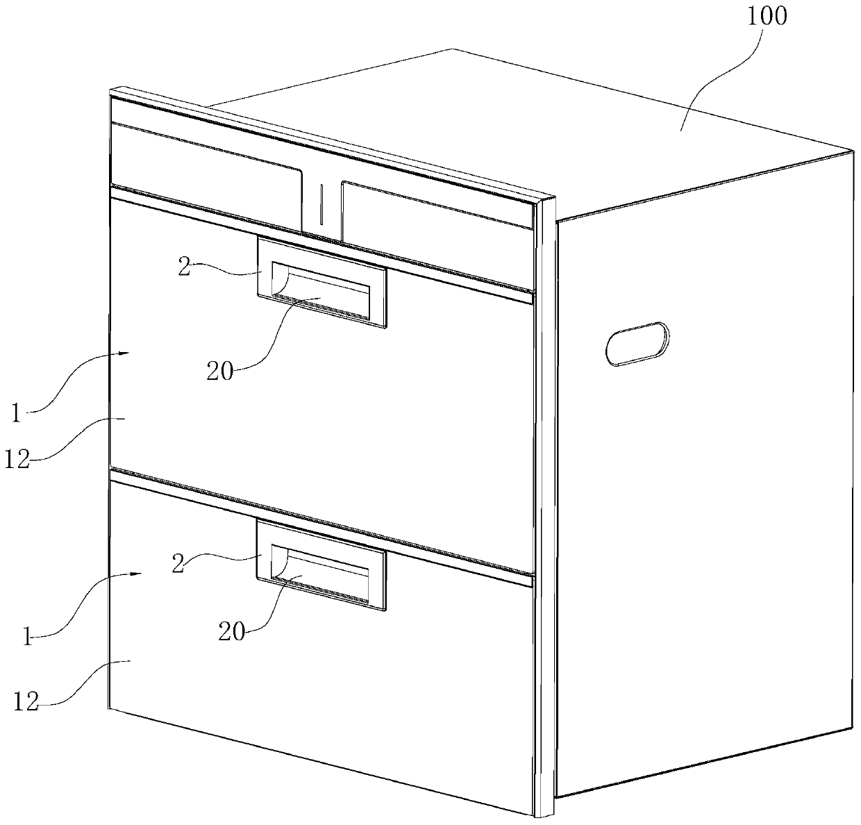
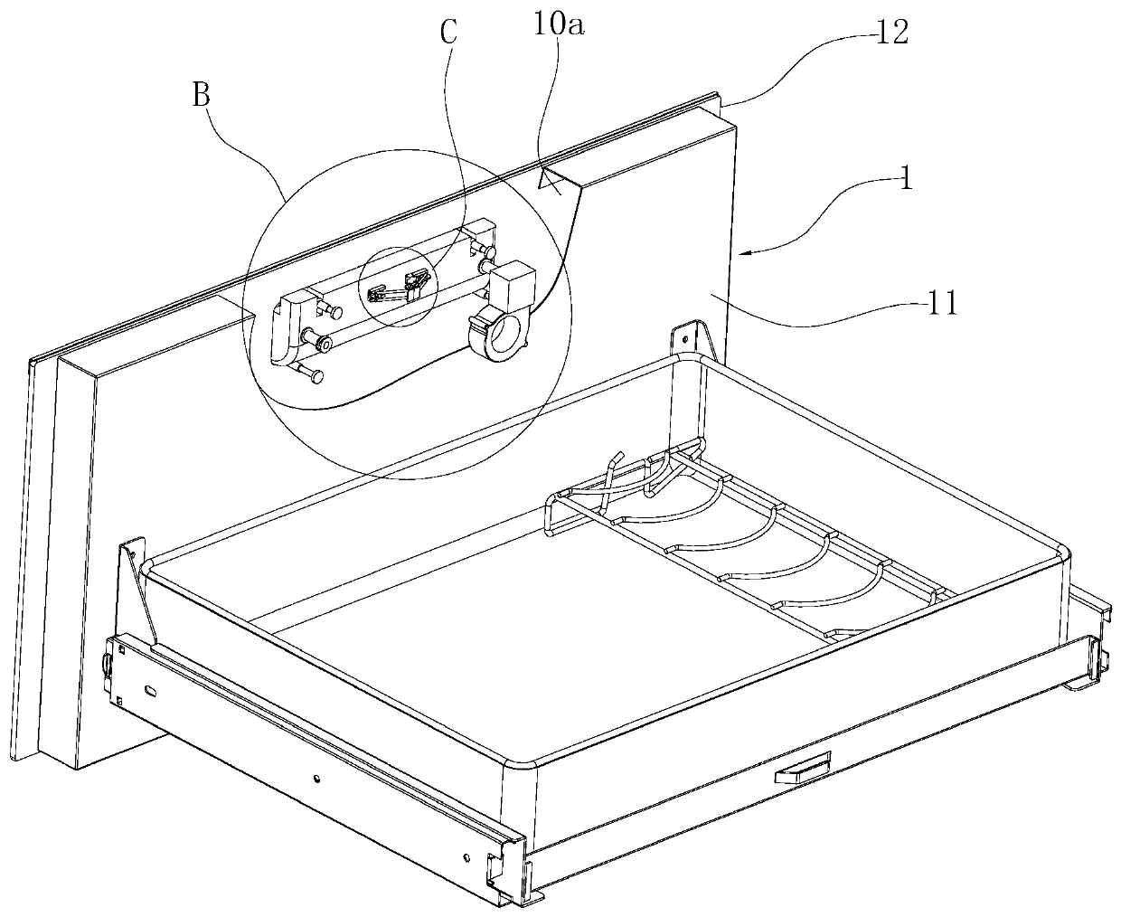
[0029] Such as Figure 1-10As shown, a disinfection cabinet includes a cabinet body 1, the front of which is open and its inner cavity is the inner container of the disinfection cabinet. In this embodiment, two drawers 10 are arranged above and below the inner container, and the drawer panels of each drawer 10 respectively constitute the door body 1 of the disinfection cabinet and cover the opening of the inner container. Each door body 1 includes a box-shaped door frame 11 and a panel 12, the panel 12 covers the opening of the door frame 11, and the panel 12 is provided with an installation opening 121, and a handle 2 is embedded in the installation opening 121, The panel 12 and the door frame 11 enclose a space 10a capable of accommodating the above-mentioned handle 2 .

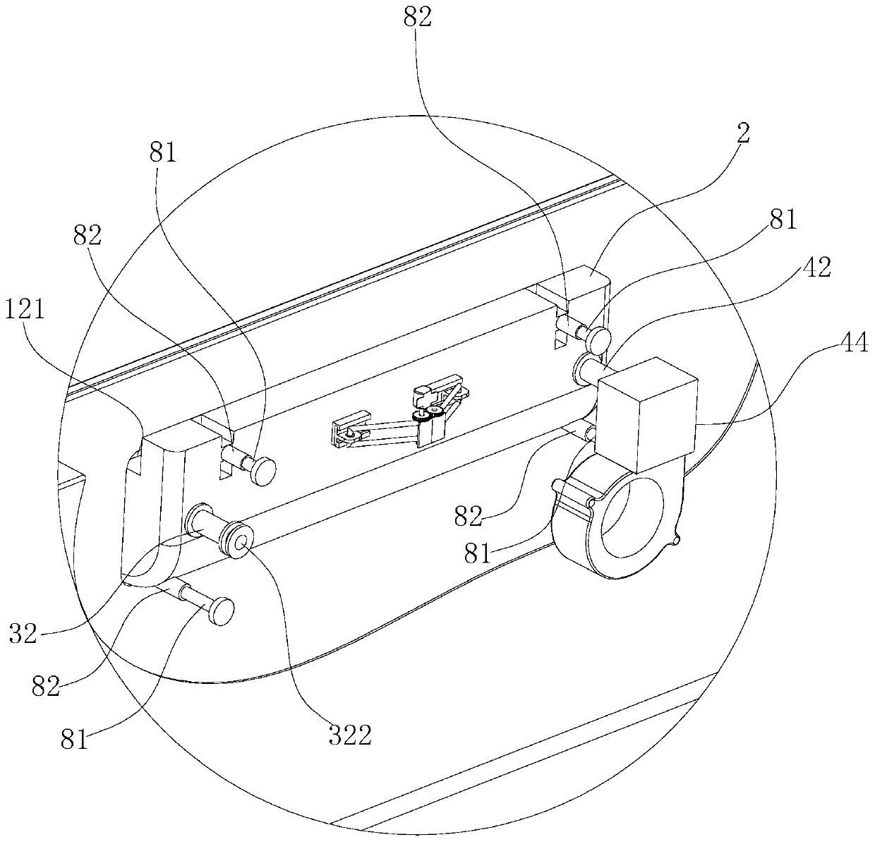
[0030] The above-mentioned handle 2 is respectively provided with an air intake mechanism 3 and an exhaust mechanism 4, wherein the air intake mechanism 3 includes an air intake chamber 31 with an air inle...

Embodiment 2

[0036] Such as Figure 11 and 12 As shown, the difference from Embodiment 1 is that in this embodiment, the upper locking ejection mechanism 6 includes a motor 61, a first connecting rod 64, a second connecting rod 65, a first slide rail 661 and a second slide rail 662. The first slide rail 661 and the second slide rail 662 are respectively fixed on the handle 2, the first hinge seat 691 and the second hinge seat 692 are respectively fixed on the above-mentioned door frame 11, and the above-mentioned first connecting rod 64 and the second connecting rod 65 are opposite to each other. Set, the first end of each connecting rod is respectively hinged with the first hinged seat 691 and the second hinged seat 692, and the second end of each connecting rod is respectively hinged with the first slider 671 and the second slider 672, the first The slider 671 and the second slider 672 are respectively embedded in the above-mentioned first slide rail 661 and the second slide rail 662 an...


PUM


Abstract

The invention relates to a disinfection cabinet. A gas inlet mechanism and a gas exhaust mechanism are separately arranged on a handle of each disinfection cabinet door body; each gas inlet mechanism comprises a gas inlet cavity having a gas inlet hole and a gas inlet pipe; each gas exhaust mechanism comprises a gas exhaust cavity having a gas exhaust hole and a gas exhaust pipe; under initial state, each gas inlet hole of the corresponding gas inlet mechanism and each gas exhaust hole of the corresponding gas exhaust mechanism are separately plugged by a first plugging piece and a second plugging piece, and a corresponding liner is under a sealing state; under the state that each handle moves forward, the corresponding gas inlet hole and the corresponding gas exhaust hole are exposed, so that external air can enter the corresponding liner through the corresponding gas inlet hole, the corresponding gas inlet cavity and the corresponding gas inlet pipe, and gas in the corresponding liner can be exhausted through the corresponding gas exhaust pipe, the corresponding gas exhaust cavity and the corresponding gas exhaust hole; and therefore, the situation that a cupboard of the disinfection cabinet is decomposed, mildewed and rotted because exhausted steam is accumulated in the cupboard can be avoided through front ventilation especially front exhaust of the disinfection cabinet. The opening and the closing of ventilation holes can be realized through moving the handles, so that the operation is convenient, and besides, the leakage of disinfection gas (such as ozone and the like) can be avoided.

Description

technical field [0001] The invention relates to the field of household appliances, in particular to a disinfection cabinet. Background technique [0002] With the improvement of living standards, tableware disinfection cabinets have gradually entered people's daily lives. Heating is a commonly used technical method for disinfection cabinets. Generally, at the end of disinfection, high-temperature sterilization and rapid decomposition of ozone are achieved through heating. During the heating process, the water on the surface of tableware and in the inner container is evaporated into water vapor. For this reason, it is necessary to discharge ozone, water vapor, etc. in the end stage of disinfection. The exhaust system in the existing disinfection cabinet is generally arranged on the back of the disinfection cabinet. ) of the Chinese invention patent discloses a disinfection cabinet, the upper right side of the back of the cabinet is provided with an exhaust port, the inner bo...

Claims


Application Information

Patent Timeline
Patent Type & Authority Applications(China)
IPC IPC(8): A61L2/26A61L2/20
CPCA61L2/202A61L2/26
Inventor 黄鹏袁柯铭
Owner NINGBO FOTILE KITCHEN WARE CO LTD
Why Eureka
Try Eureka