Automobile part stamping die

A technology for stamping dies and auto parts, applied to forming tools, manufacturing tools, metal processing equipment, etc., can solve problems such as unusable, increased production costs of auto parts, deformation of forming dies, etc.

Inactive Publication Date: 2019-09-17
北京和信汽车部件有限公司
View PDF10 Cites 1 Cited by
  • Summary
  • Abstract
  • Description
  • Claims
  • Application Information

AI Technical Summary

Problems solved by technology

In order to ensure that the stripping rod can separate the molding parts from the mold, the stripping rods are mostly made of hard metal materials. When the stripping rod demolds the molding parts, the rigid contact between the stripping rod and the molded mold is easy to make The forming mold is deformed. Since auto parts require high assembly accuracy during assembly, the deformed parts need to be repaired, adjusted or even unusable during assembly, thereby increasing the production cost of auto parts

Method used


Image

  • Automobile part stamping die
  • Automobile part stamping die
  • Automobile part stamping die

Examples


Embodiment 1

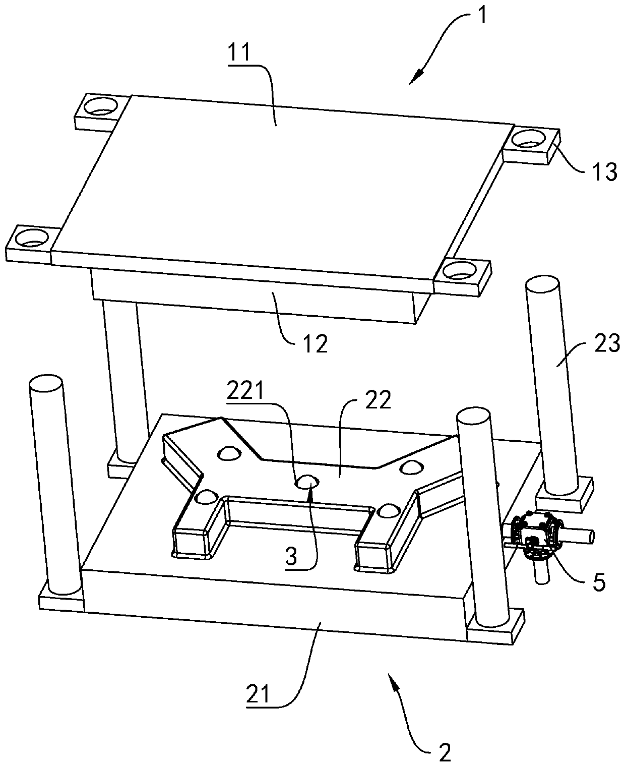
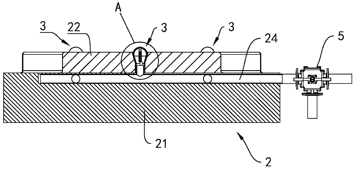
[0037] refer to figure 1 , is a stamping die for auto parts disclosed in the present invention, comprising an upper die 1 and a lower die 2 that are opposite up and down. The upper mold 1 includes an upper mold base 11 and a concave mold 12 located on the bottom surface of the upper mold base 11 , and the concave mold 12 is integrally formed with the upper mold base 11 . The lower mold 2 includes a lower mold base 21 and a punch 22 located on the top surface of the lower mold base 21 , and the punch 22 and the lower mold base 21 are integrally formed. The die 12 and the punch 22 on the upper die 1 and the lower die 2 are arranged oppositely. On opposite sides of the lower mold base 21, vertically arranged guide rods 23 are arranged, and the guide rods 23 are fixedly connected with the lower mold base 21. A sliding sleeve 13 is fixed at a position opposite to the guide rod 23 on the upper die base 11 , and the top end of the guide rod 23 runs through the sliding sleeve 13 and...

Embodiment 2

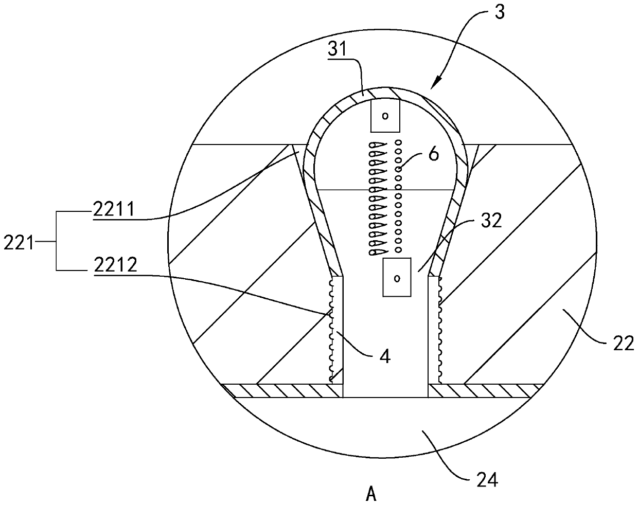
[0048] refer to Figure 5 , is a stamping die for auto parts disclosed by the present invention. The difference between Embodiment 2 and Embodiment 1 is that a counterweight 7 is arranged inside the inflatable airbag 3 , and the counterweight 7 is fixed on the closed end of the inflatable airbag 3 . Due to the weight of the counterweight 7 , during the deflation process of the inflatable airbag 3 , the counterweight 7 falls under gravity, so that the inflatable airbag 3 is quickly retracted into the accommodation hole 221 .


PUM


Abstract

The invention relates to an automobile part stamping die. The automobile part stamping die comprises an upper die body and a lower die body which are opposite to each other up and down. The upper die body comprises an upper die holder and a female die portion. The lower die body comprises a lower die holder and a male die portion. The female die portion and the male die portion are opposite to each other. The surface of the male die portion is provided with a plurality of accommodating holes. Inflatable air bags are arranged in the accommodating holes and expand and stretch out of hole openings of the accommodating holes when being inflated. An inflating channel is formed in the male die portion and communicates with the inflatable air bags located in the accommodating holes. A three-way valve is arranged at the air inlet end of the inflating channel. One connecting port of the three-way valve communicates with the inflating channel, one connecting port communicates with an air source, and the remaining connecting port serves as an exhaust port. The automobile part stamping die has the characteristic that when a formed part is demoulded through a demoulding device, the formed part is not prone to deformation.

Description

technical field [0001] The invention relates to the technical field of auto parts production, in particular to a stamping die for auto parts. Background technique [0002] With the advancement of science and technology in our country and the rapid development of the national economy, automobiles have become an indispensable means of transportation in daily life. Among them, the efficiency and quality of mass production of auto parts have become a favorable means of competition in today's market. Therefore, for The requirements of the mold industry in the automotive field are also increasing. [0003] Automobile sheet metal parts are mostly produced by stamping, which requires special punches and dies. After the stamping part is formed, the opposite surface of the stamping part and the punch will stick due to the pressure, and there is friction between the folded surface of the stamping part and the punch. When separating the stamping part from the punch, it is necessary to...

Claims


Application Information

Patent Timeline
Patent Type & Authority Applications(China)
IPC IPC(8): B21D37/10B21D45/02B21D22/02B21D37/12
CPCB21D22/02B21D37/10B21D37/12B21D45/02
Inventor 金荣乭
Owner 北京和信汽车部件有限公司
Why Eureka
Try Eureka