Self-propelled wire boring device for inner wall of through pipe

A wall boring and self-advancing technology, which is applied in the field of self-advancing through-pipe inner wall boring devices, can solve the problem of low degree of automation and achieve the effect of wide application range and easy pick and place.

Inactive Publication Date: 2019-09-17
马单智
View PDF12 Cites 3 Cited by
  • Summary
  • Abstract
  • Description
  • Claims
  • Application Information

AI Technical Summary

Problems solved by technology

[0003] However, the existing threading machines can only process the outer wall of the pipe, and the internal thread needs to be processed by the principle of a boring machine. Since there is no special machine tool, manual feeding is required during work, and the degree of automation is not high.

Method used


Image

  • Self-propelled wire boring device for inner wall of through pipe
  • Self-propelled wire boring device for inner wall of through pipe
  • Self-propelled wire boring device for inner wall of through pipe

Examples


Embodiment 1

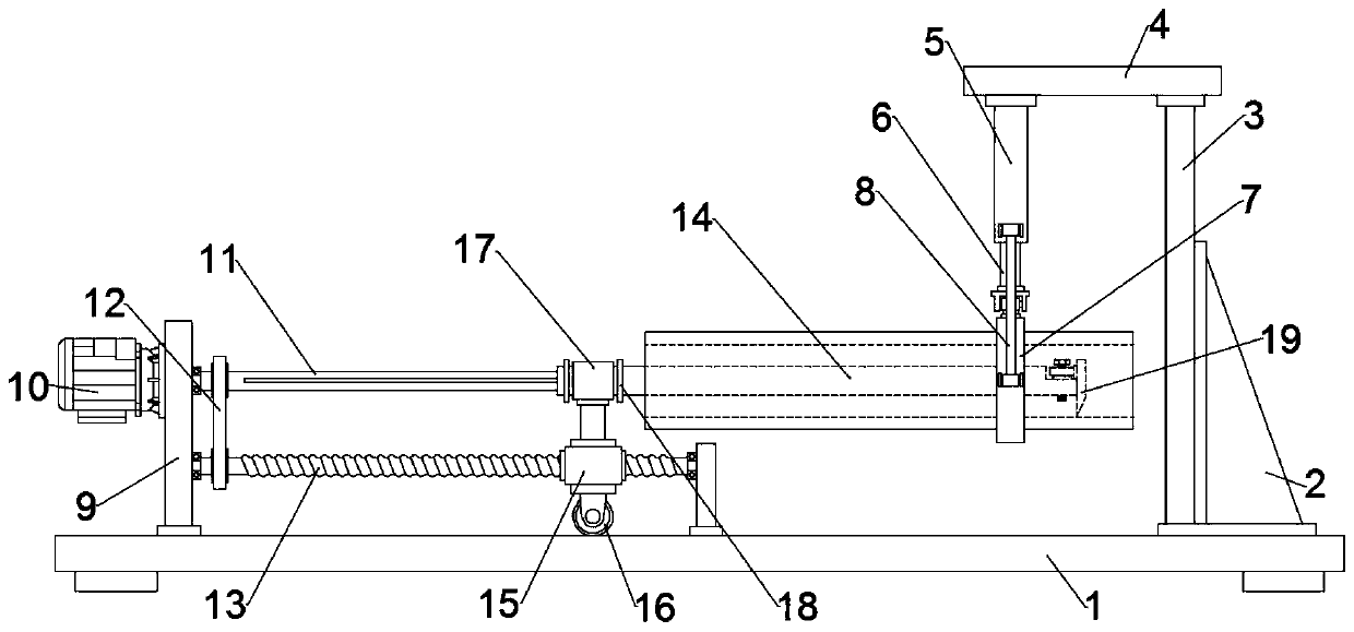
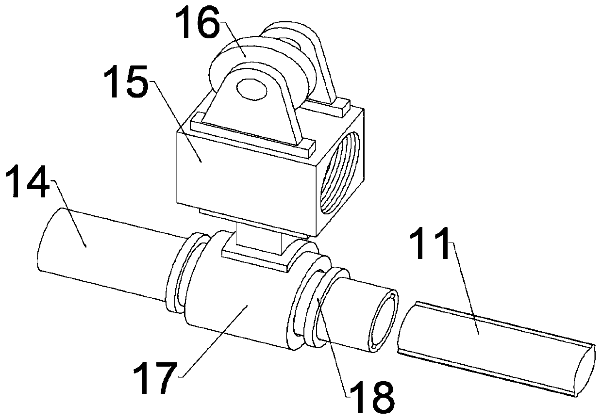
[0021] see Figure 1~3 , in an embodiment of the present invention, a self-propelled through-pipe inner wall boring device includes a workbench 1, a clamping device installed above one side of the workbench 1 for fixing the through-pipe, a tapping assembly and a push tapping Traveling mechanism for component travel;

[0022] Specifically, the clamping device is fixed below the top plate 4, the top plate 4 is fixed on one side of the workbench 1 through the support plate 3, and a reinforcing rib 2 is fixed at the connection between the workbench 1 and the support plate 3, and the clamping The device suspends and fixes the through pipe, which is convenient for processing; on the side of the workbench 1 opposite to the support plate 3, a mounting plate 9 for flange mounting of the servo motor 10 is fixed, and the servo motor 10 is connected to the power supply and the switch through a wire, and the servo motor The output end of 10 is connected to the drive shaft 11. It should be...

Embodiment 2

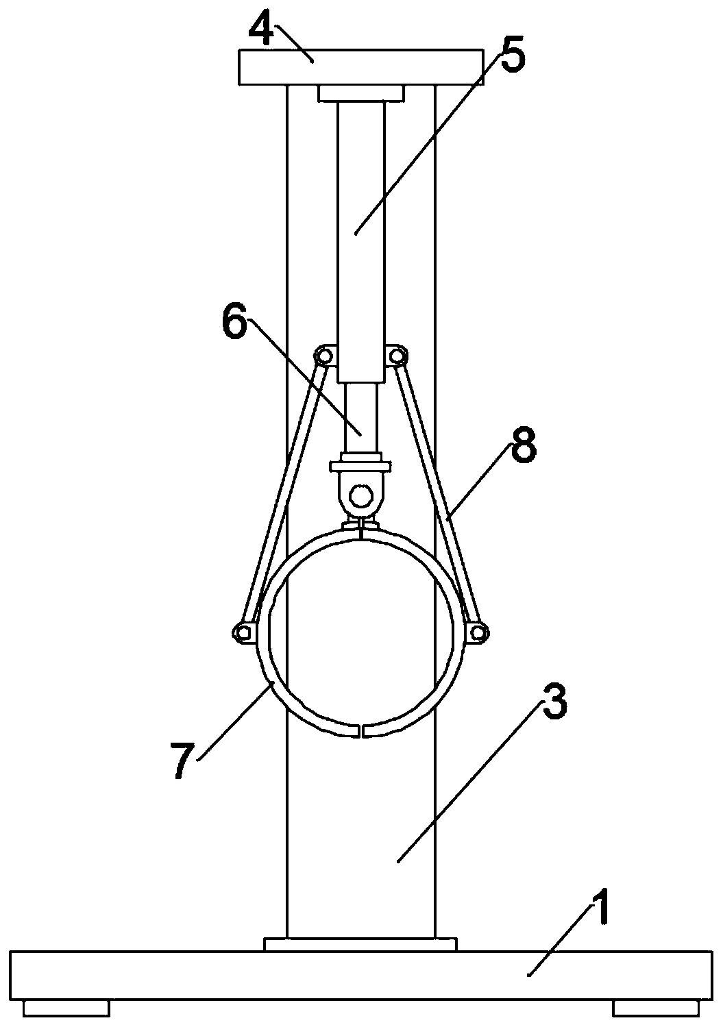
[0026] In order to further describe the clamping device in the above-mentioned embodiment in detail, the present application provides another embodiment, a self-propelled through-pipe inner wall boring device, the clamping device includes a driving mechanism fixed on the top plate 4, The piston rod 6 slidably connected to the lower part of the driving mechanism, and the two clamping claws 7 hinged at the lower end of the piston rod 6. Preferably, the driving mechanism is a cylinder 5. Obviously, the driving mechanism is not limited to the cylinder 5, and can also be a hydraulic cylinder, etc. , the lower end of the connecting rod 8 is hinged at the middle part of the outer wall of the clamping turn 7, and the upper end of the connecting rod 8 is hinged on the outer wall of the lower part of the cylinder 5. stretching, thereby driving the upper hinge of the clamping claw 7 to move, and under the action of the connecting rod 8, the clamping claws 7 on both sides are driven to ope...


PUM


Abstract

The invention discloses a self-propelled wire boring device for an inner wall of a through pipe, in particular to a device which drives a sleeve pipe to move horizontally along a moving block through the cooperation of a sleeve ring and a flange, realizes the automatic feeding function and realizes boring an inner wire along the rotation and walking of a boring tool through cooperating with the rotating sleeve pipe; and the self-propelled wire boring device for the inner wall of the through pipe solves the problem that the existing tapping machine needs to be divided and promoted and the degree of automation is not high. A clamping device is fixed at the lower part of a top plate; the top plate is fixed at one side of a workbench through a support plate; one side, relative to the support plate, of the workbench is fixed with an installation plate for installing a servo motor by the flange; the servo motor is connected with a power source and a switch through a wire, and the output end of the servo motor is connected with a driving shaft; a tapping assembly is arranged on the driving shaft; the tapping assembly comprises the sleeve pipe sleeved and nested on the driving shaft and the boring tool detachably connected at the end of the sleeve pipe by a thread, wherein the lower part of the sleeve pipe is connected with a walking mechanism.

Description

technical field [0001] The invention relates to a workpiece processing equipment, in particular to a self-propelled through-pipe inner wall boring device. Background technique [0002] With the in-depth development of economic construction, the threading machine has wide applicability, and can thread pipes, bars, and steel bars. Specifically, the traditional manual pipe thread twister is electrified, which makes pipe thread processing during pipe installation It becomes easy and fast, and reduces the labor intensity of pipeline installation workers. It is suitable for mass production of steel pipe factories, mining bureaus, construction, bridges, railways, electric power and other related enterprises. Its product advantages lie in high precision, high productivity and advanced technology. [0003] However, the existing threading machines can only process the outer wall of the pipeline, and the internal thread needs to be processed using the principle of a boring machine. Si...

Claims


Application Information

Patent Timeline
Patent Type & Authority Applications(China)
IPC IPC(8): B23G1/22B23G1/44
CPCB23G1/22B23G1/44
Inventor 马单智
Owner 马单智
Why Eureka
Try Eureka