Al technical title is built by PatSnap Al team. It summarizes the technical point description of the patent document.
A laser cladding and wire technology, applied in the field of laser cladding, can solve the problems of increasing dilution rate, de-filamentation, and many defects, and achieve the effect of prolonging service life and good insulation
Pending Publication Date: 2019-09-17
SHAANXI TIANYUAN MATERIALS PROTECTION TECH
View PDF0 Cites 2 Cited by
Summary
Abstract
Description
Claims
Application Information
AI Technical Summary
This helps you quickly interpret patents by identifying the three key elements:
Problems solved by technology
Method used
Benefits of technology
Problems solved by technology
[0002] Parts corrosion is the main cause of damage to mechanical equipment. The quality of the anti-corrosion ability of parts is directly related to the safe operation of mechanical equipment. It is a recently developed anti-corrosion technology to clad alloy powder on the surface of the workpiece by laser, but the use of alloy Powder laser cladding technology still has problems such as low cladding efficiency, many defects, high cost, and large dust.
[0003] Laser cladding of wire material can solve the above problems very well, but due to the influence of the base material and welding wire on the laser absorption rate, non-fusion phenomenon often occurs. For this phenomenon, the laser power can be increased, but increasing the laser power will cause Increase the dilution rate and cause a waste of energy, so if the welding wire can be heated before entering the molten pool, the above problems can be solved very well, and a high-quality fusion effect can be achieved without increasing the laser power. The heating effect of the heating wire device for preheating the welding wire is not good, and the phenomenon of wire jamming or wire stripping often occurs, resulting in the inability to work continuously for a long time, which hinders the development of laser cladding technology for wire materials
Method used
Image
Click on the blue label to locate the original text in one second.
Reading with bidirectional positioning of images and text.
Examples
Embodiment 1
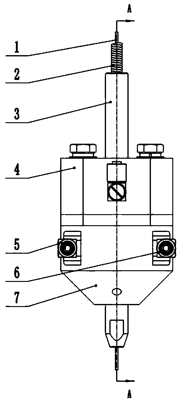
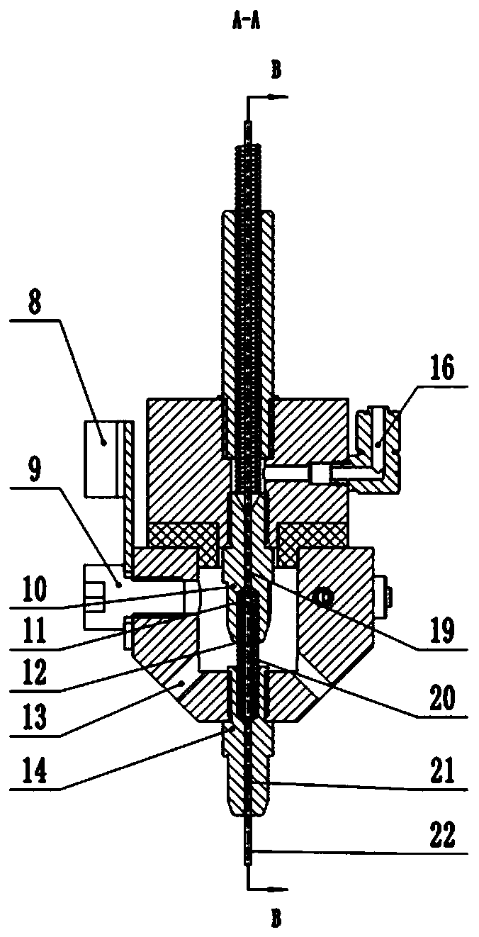
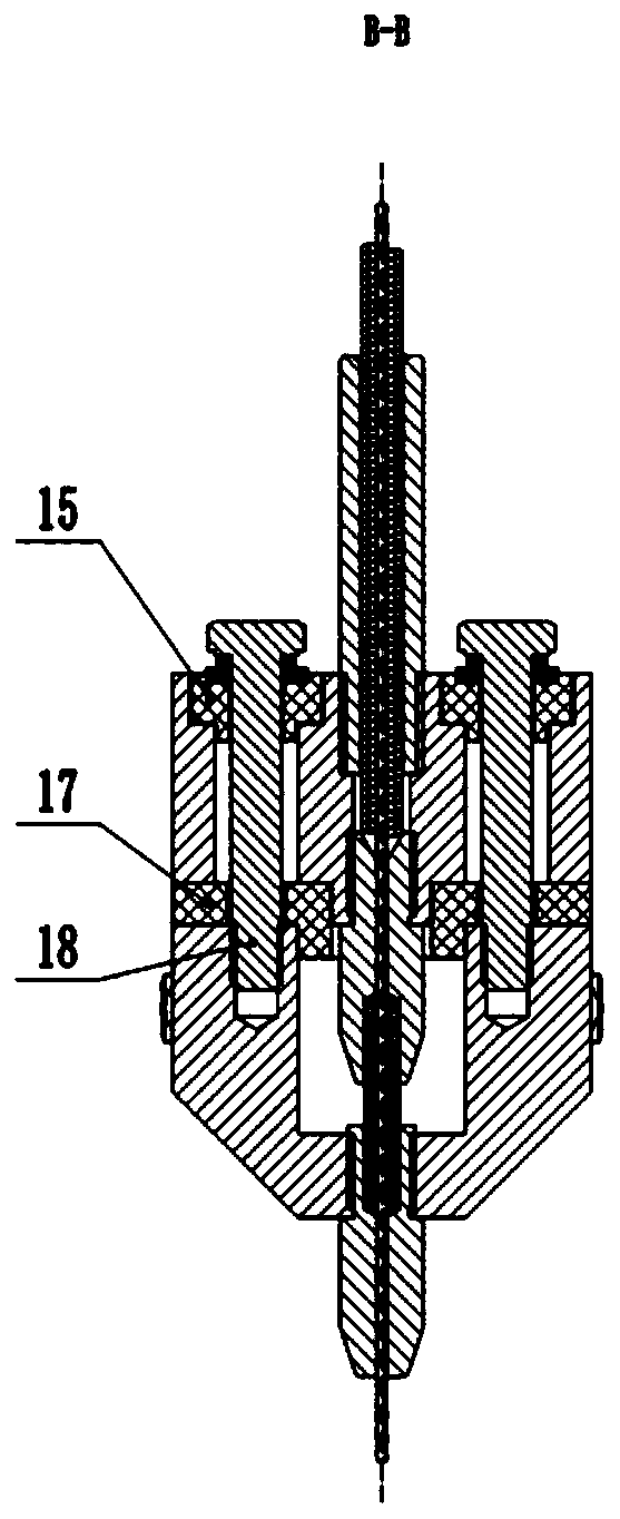
[0037] In this embodiment, the wire laser cladding hot wire device described in the present invention is used for welding wire heating, specifically for a cylindrical welding wire. The welding wire from the wire feeder passes through the wire feeding tube 2, the first conductive Nozzle 10, spring 11, insulating tube 12, second conductive tip 14 are finally sent out.
[0038] In this example, the first conductive tip 10 and the second conductive tip 14 are respectively connected to the two electrodes of the hot wire machine, and the hot wire machine is connected to form a current loop through the welding wire 1 between the two, and the welding wire itself has a certain resistance. , the interaction of current and resistance makes the welding wire 1 generate heat energy to play a hot wire effect.
[0039] In this example, the insulating tube 12 is resistant to high temperature, has an inner diameter larger than that of the welding wire 1 and forms a clearance fit with the weldin...
PUM
Abstract
The invention provides a wire laser cladding hot wire device. The device comprises a wire conveying pipe, a connecting rod, a flange, an insulating plate, an insulating pad, a water cooling head, a first conductive nozzle, a second conductive nozzle, an insulating pipe and a bolt; the connecting rod is connected to the flange, the wire conveying pipe is arranged in the connecting rod, the insulating plate is arranged between the flange and the water cooling head, the insulating pad is arranged between the flange and the bolt, the bolt sequentially penetrates through the insulating pad, the flange and the insulating plate and then is in threaded connection with the water cooling head, the first conductive nozzle is installed on the flange, the second conductive nozzle is installed on the water cooling head, and the insulating pipe is arranged between the first conductive nozzle and the second conductive nozzle. According to the wire laser cladding hot wire device, a heating structure of the hot wire device is innovatively arranged, so that the heating effect of the hot wire is improved, the highest temperature can reach 1000 DEG C, continuous and stable heating can be realized, the requirements of automatic continuous production are met, wire passing is smooth and wire blocking can be avoided, the structure is firm, deformation and shaking during long-time operation can be avoided, and the bottleneck problem of an existing wire laser cladding technology can be solved.
Description
technical field [0001] The invention relates to the technical field of laser cladding, in particular to a hot wire device for laser cladding of wire materials. Background technique [0002] Parts corrosion is the main cause of damage to mechanical equipment. The quality of the anti-corrosion ability of parts is directly related to the safe operation of mechanical equipment. It is a recently developed anti-corrosion technology to clad alloy powder on the surface of the workpiece by laser, but the use of alloy Powder laser cladding technology also has problems such as low cladding efficiency, many defects, high cost, and large dust. [0003] Laser cladding of wire material can solve the above problems very well, but due to the influence of the base material and welding wire on the laser absorption rate, non-fusion phenomenon often occurs. For this phenomenon, the laser power can be increased, but increasing the laser power will cause Increase the dilution rate and cause a was...
Claims
Application Information
Patent Timeline
Application Date:The date an application was filed.
Publication Date:The date a patent or application was officially published.
First Publication Date:The earliest publication date of a patent with the same application number.
Issue Date:Publication date of the patent grant document.
PCT Entry Date:The Entry date of PCT National Phase.
Estimated Expiry Date:The statutory expiry date of a patent right according to the Patent Law, and it is the longest term of protection that the patent right can achieve without the termination of the patent right due to other reasons(Term extension factor has been taken into account ).
Invalid Date:Actual expiry date is based on effective date or publication date of legal transaction data of invalid patent.