
Floor overhead leveling device and laying method thereof

A floor and air-conditioning technology, which is applied to local access floors, floors, buildings, etc., can solve problems such as difficulty in meeting acceptance requirements, long leveling cycle, waste of resources, etc., to achieve shortened leveling cycle, high adjustment efficiency, and high flatness Effect

Pending Publication Date: 2019-09-17
ZHEJIANG YASHA DECORATION
View PDF0 Cites 5 Cited by
  • Summary
  • Abstract
  • Description
  • Claims
  • Application Information

AI Technical Summary

Problems solved by technology

In the process of realizing the invention, the inventor found that the above-mentioned ground leveling and floor installation have the following shortcomings: when self-leveling is used for leveling, due to the relatively poor fluidity of cement mortar, it is difficult to achieve the acceptance of flatness ± 2mm after leveling the cement mortar requirements, the leveling effect needs to be improved; second, the use of cement mortar for leveling generally requires 3-7 days of curing time, and the leveling cycle is long, which slows down the construction progress; third, once the floor is attached to the ground, it cannot be damaged. demolition, waste of resources

Method used


Image

  • Floor overhead leveling device and laying method thereof
  • Floor overhead leveling device and laying method thereof
  • Floor overhead leveling device and laying method thereof

Examples


Embodiment Construction

[0027] The directional terms such as up, down, left, right, front, back, front, back, top, and bottom that are mentioned or may be mentioned in this specification are defined relative to the structures shown in the drawings. The words " "Inside" and "outside" respectively refer to the direction toward or away from the geometric center of a specific component. They are relative concepts, so they may change accordingly according to their different positions and different usage states. Accordingly, these or other directional terms should not be construed as limiting terms.

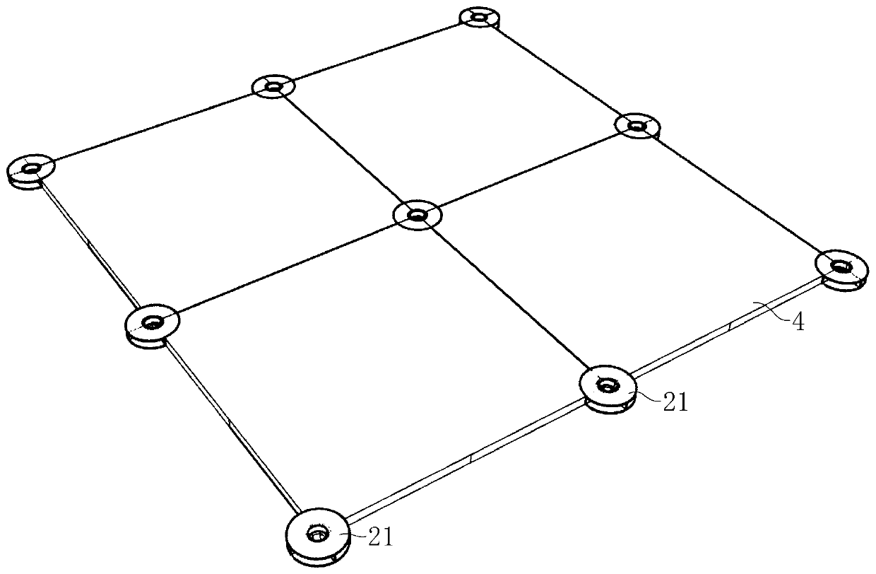
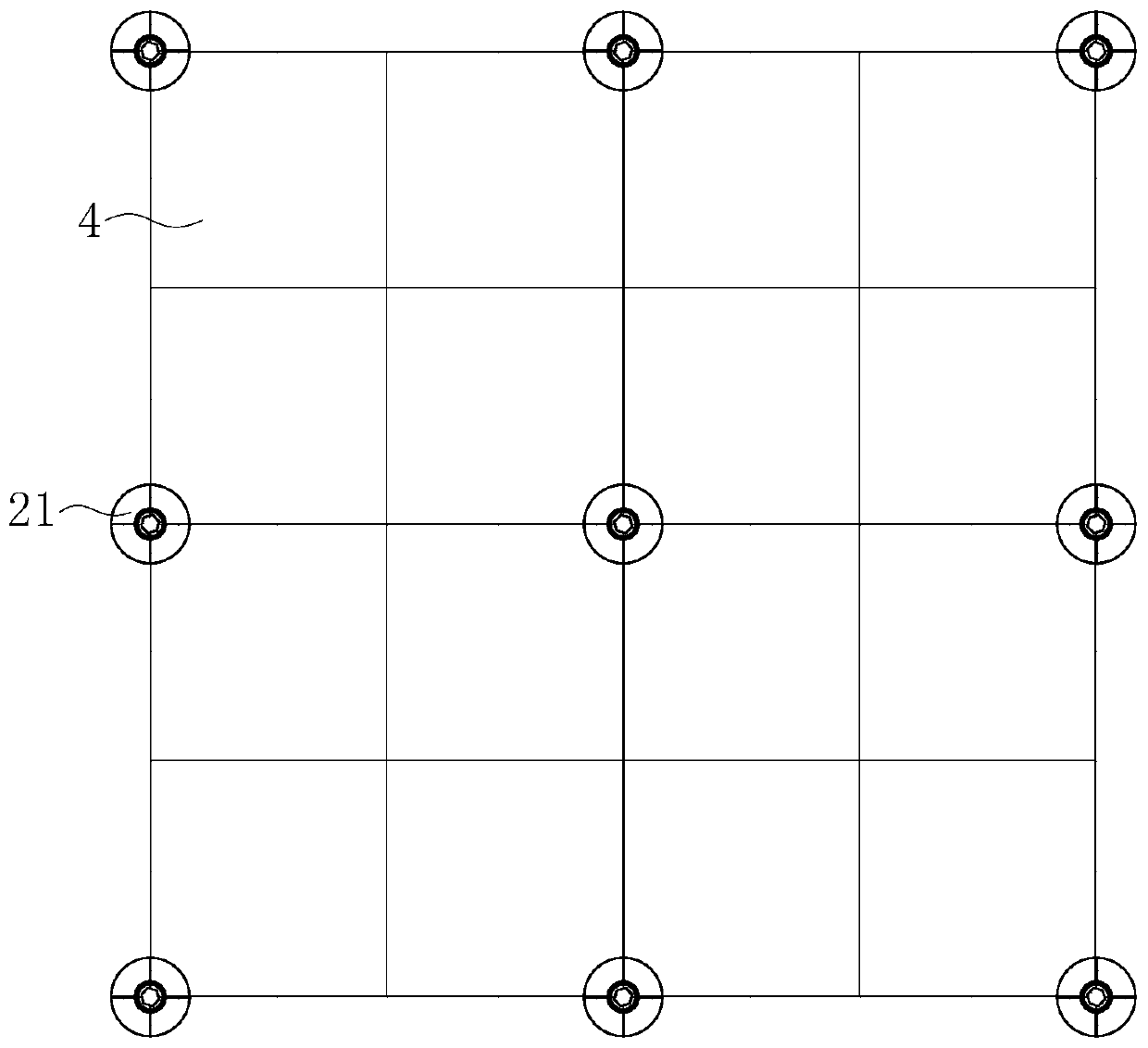
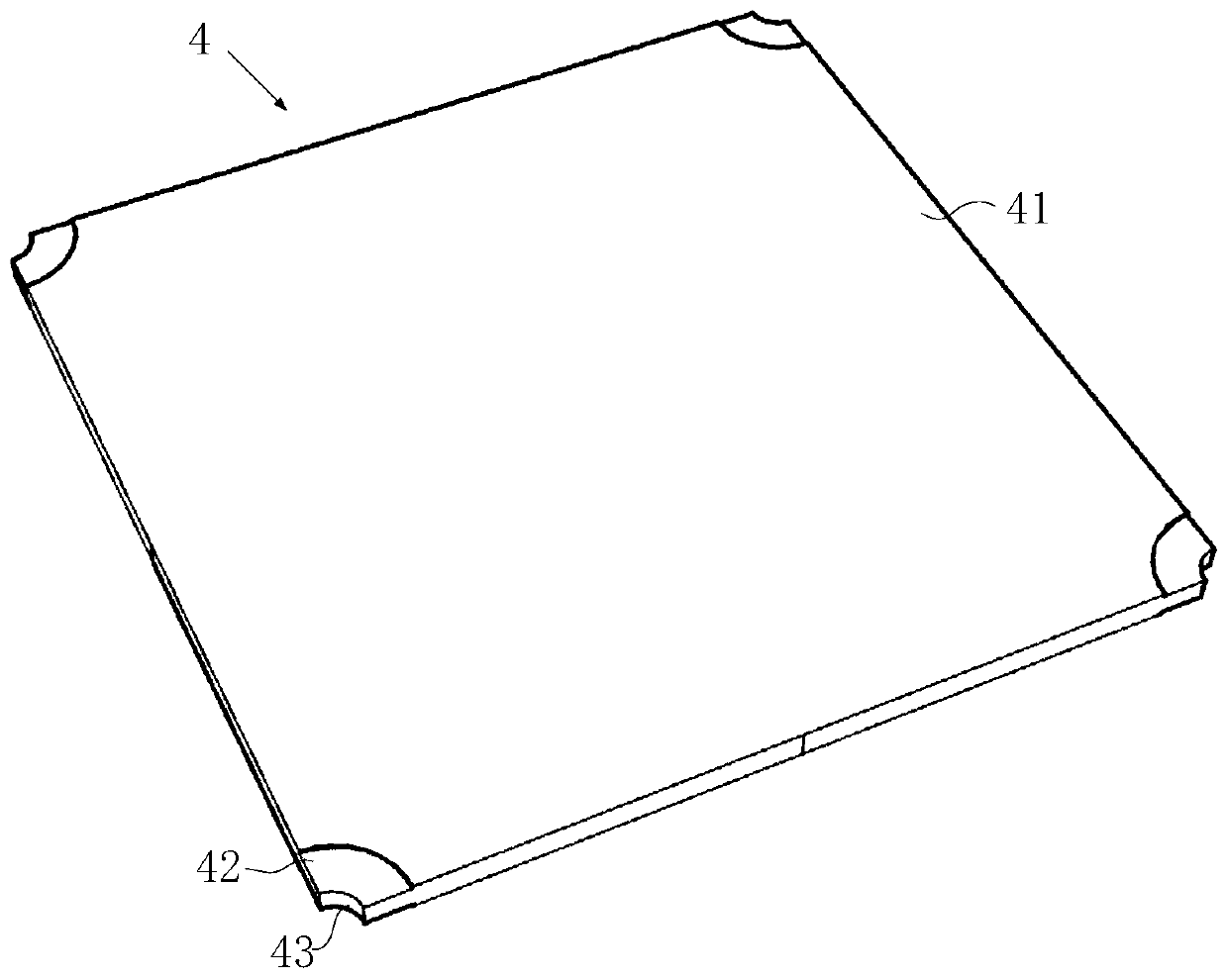
[0028] figure 1 A schematic structural view of a floor rack leveling device provided in an optional embodiment of the present invention, figure 2 for figure 1 top view of image 3 A schematic structural view of the floor provided in an optional embodiment of the present invention, Figure 4 A schematic structural view of the leveling foot provided for an optional embodiment of the present invention, Fi...


PUM


Abstract

The invention discloses a floor overhead leveling device and a laying method thereof. The floor overhead leveling device is characterized in that leveling bases comprise leveling plates and limiting columns vertically mounted on the leveling plates; the limiting columns are provided with first threaded holes in the axial direction, wherein the first threaded holes penetrate through the limiting columns and the leveling plates simultaneously; leveling covers comprise cover plates and adjusting columns vertically mounted on the cover plates, and second threaded holes are formed in the adjusting column in the axial direction, wherein the second threaded holes penetrate through the adjusting columns and the leveling covers simultaneously; first outer threads matched with the first threaded holes are arranged on the outer axial faces of the adjusting columns, and the adjusting columns are connected into the first threaded holes in a threaded mode; adjusting screws are connected into the second threaded holes in a threaded mode; and top corners of floors are detachably embedded between the leveling plates and the cover plates. The laying method of the floor overhead leveling device is used for laying the floor overhead leveling device. According to the floor overhead leveling device and the laying method thereof, the ground is rapidly leveled, the flatness of the mounted floors is ensured, the leveling period is shortened, the mounted floors can be demounted nondestructively, and sources are saved.

Description

technical field [0001] The invention relates to the technical field of architectural decoration, in particular to a floor frame air leveling device and a laying method. Background technique [0002] In indoor and outdoor decoration, the entire ground needs to be leveled before installing the floor, so that after the floor is installed on the ground, the flatness of the floor meets the architectural requirements. [0003] In the prior art, before the floor is installed, the ground generally needs to be leveled by self-leveling cement mortar, and then the cement mortar is fixed to fit the floor. In the process of realizing the invention, the inventor found that the above-mentioned ground leveling and floor installation have the following shortcomings: when self-leveling is used for leveling, due to the relatively poor fluidity of cement mortar, it is difficult to achieve the acceptance of flatness ± 2mm after leveling the cement mortar requirements, the leveling effect needs ...

Claims


Application Information

Patent Timeline
IPC IPC(8): E04F15/024
CPCE04F15/02044E04F2015/02127
Inventor 王文广丁欣欣丁泽成周东珊高宇臻余广
Owner ZHEJIANG YASHA DECORATION
Learn More