Centralized water gate group monitoring device

A monitoring device, a centralized technology, applied in valve devices, measuring devices, lubrication indicating devices, etc., can solve the problems of inability to monitor dynamic video of sluice gates, inability to monitor water level rising speed in advance, and inability to achieve preventive management in advance, etc. The effect of monitoring range, reducing monitoring blind spot, and convenient management

Inactive Publication Date: 2019-09-17
广州市浩图信息科技有限公司
View PDF0 Cites 2 Cited by
  • Summary
  • Abstract
  • Description
  • Claims
  • Application Information

AI Technical Summary

Problems solved by technology

[0004] The purpose of the present invention is: in order to solve the problem that the existing centralized sluice group monitoring device can only monitor the water level near the sluice, but cannot monitor the rising speed of the water level in advance, so that it cannot achieve preventive management in advance, and at the same time cannot monitor Video monitoring of the dynamics near the sluices cannot detect problems and problems in a timely manner, so the proposed centralized sluice group monitoring device

Method used


Image

  • Centralized water gate group monitoring device
  • Centralized water gate group monitoring device
  • Centralized water gate group monitoring device

Examples


Embodiment 1

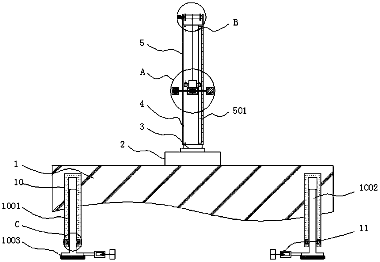
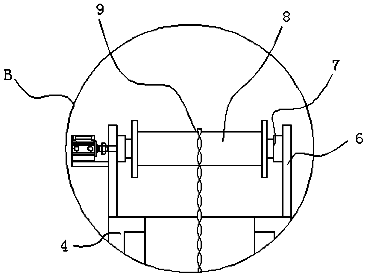
[0042] see Figure 1-7, a centralized sluice group monitoring device, including a sluice main body 1, a water level rising speed monitoring mechanism 10 and a self-cleaning mechanism 12, a control box 2 is arranged on the upper end of the sluice main body 1, and a first rotating shaft 3 is arranged on the upper end of the control box 2, The upper end of the first rotating shaft 3 is inlaid with a support tube 4, and the front of the support tube 4 is connected with a video monitoring mechanism 5, and the upper end of the support tube 4 is equipped with a support frame 6, and the inner two sides of the support frame 6 are fixed with a second The rotating shaft 7 and the end of the second rotating shaft 7 close to the centerline of the support frame 6 are provided with a reel 8, and the front of the reel 8 is provided with a steel chain 9, and the water level rising speed monitoring mechanism 10 is embedded in the front of the sluice main body 1 On both sides, and the end of the...

Embodiment 2

[0044] see figure 1 , the support tube 4 constitutes a rotating structure through the first rotating shaft 3 and the control box 2, and the control box 2 is fixedly connected to the main body 1 of the sluice, the supporting tube 4 can rotate along the first rotating shaft 3, then it can take its The monitoring probe 506 at the upper end rotates horizontally, so that the surroundings of the water gate can be monitored in a large area, the monitoring range of the water gate can be increased, and the monitoring blind area can be reduced.

Embodiment 3

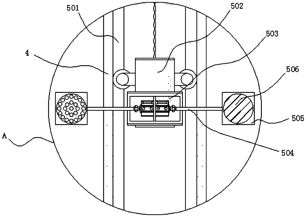
[0046] see figure 1 with 2 , the inside of the video monitoring mechanism 5 includes a chute 501, and an integral connection is formed between the chute 501 and the inner wall of the support tube 4 by injection molding, the inside of the support tube 4 is provided with a sliding frame 502, and the front side of the sliding frame 502 is welded There is a first chassis 503, and drive shafts 504 are arranged on both sides of the interior of the first chassis 503, and an installation box 505 is inlaid on the end of the drive shaft 504 away from the center line of the first chassis 503, and a monitoring probe 506 is connected inside the installation box 505, Sliding frame 502 is connected with steel chain 9, is movable connection between cylinder 1005 and movable plate 1002, and is sliding connection between movable plate 1002 and fixed plate 1001, and cylinder 1005 is symmetrical about the central line of fixed plate 1001, and its cylinder 1005 The rotating structure is formed by...


PUM


Abstract

The invention discloses a centralized water gate group monitoring device, and relates to the technical field of water gate management. The centralized water gate group monitoring device comprises a water gate main body, water level ascending speed monitoring mechanisms and a self-cleaning mechanism; a control box is arranged at the upper end of the water gate main body; a first rotating shaft is placed at the upper end of the control box; a support pipe is embedded in the upper end of the first rotating shaft; the front surface of the support pipe is connected with a video monitoring mechanism; a support frame is mounted at the upper end of the support pipe; second rotating shafts are fixed at the upper ends of the two sides in the support frame; winding drums are arranged at the ends, near the center line of the support frame, of the second rotating shafts; steel chains are placed on the front surfaces of the winding drums; and the water level ascending speed monitoring mechanisms are embedded in the two sides of the front surface of the water gate main body. In the centralized water gate group monitoring device, the support pipe can be rotated along the first rotating shaft to drive a monitoring probe at the upper end thereof to horizontally rotate, so that the wide-range monitoring of the surroundings of water gates can be achieved, the monitoring range of the water gates is widened, and monitoring blind areas are reduced.

Description

technical field [0001] The invention relates to the technical field of sluice management, in particular to a centralized monitoring device for sluice groups. Background technique [0002] With the rapid development of the national economy, water conservancy projects are playing an increasingly important role in the national economy. Flood control is an important aspect that directly affects the development of the national economy. Due to the low level of flood control informatization, errors in previous manual observation data Large, difficult system maintenance, easy to miss major events. Once there is an abnormal weather, the flood control safety of major reservoirs and sluices is worrying, and it also puts huge pressure on urban flood control. The geographical range is relatively wide, the monitoring points are relatively scattered, and there are many network monitoring users. Each water conservancy department needs to supervise at various levels, and for large-scale mon...

Claims


Application Information

Patent Timeline
Patent Type & Authority Applications(China)
IPC IPC(8): F16M11/04F16M11/12F16M11/18F16K37/00G01F23/00B08B1/04H04N7/18H04N5/225
CPCF16M11/04F16M11/121F16M11/18F16K37/0091G01F23/00B08B1/04B08B1/002H04N7/18H04N23/52
Inventor 杨志波
Owner 广州市浩图信息科技有限公司
Why Eureka
Try Eureka