
Metal and glass packaging sintering furnace

A technology of glass encapsulation and sintering furnace, applied in the direction of furnace, furnace cooling, furnace components, etc., can solve the problems of large influence of furnace tube, low production efficiency, increased energy loss, etc., and achieve mass production, high production efficiency, The effect of using time

Active Publication Date: 2019-09-17
BENGBU XINGCHUANG ELECTRONICS TECH CO LTD
View PDF5 Cites 0 Cited by
  • Summary
  • Abstract
  • Description
  • Claims
  • Application Information

AI Technical Summary

Problems solved by technology

[0002] When producing the sensor base, the electrode needs to be fixed in the electrode hole through the glass sleeve, and the glass sleeve and the electrode, and the glass sleeve and the electrode hole are all connected by sintering, so as to seal the metal and the glass. The sintering is carried out in a glass sintering furnace. The two ends of the furnace tube of the traditional tube glass sintering furnace are exposed to the outside. In this way, when the temperature of the furnace tube is raised, the influence of the external temperature on the furnace tube is particularly large, which increases the loss of energy. Not conducive to responding to national energy conservation and emission reduction policies
[0003] The sintering furnace in the prior art uses a single furnace tube for sintering production, and the production efficiency is low. The furnace tube is always placed inside the furnace body, which is not conducive to the cooling of the furnace tube, and the cooling efficiency is low, which is not suitable for mass production.

Method used


Image

  • Metal and glass packaging sintering furnace
  • Metal and glass packaging sintering furnace
  • Metal and glass packaging sintering furnace

Examples


Embodiment Construction

[0019] In order to make the object, technical solution and advantages of the present invention clearer, the present invention will be further described in detail below in conjunction with the accompanying drawings and embodiments. It should be understood that the specific embodiments described here are only used to explain the present invention, not to limit the present invention.

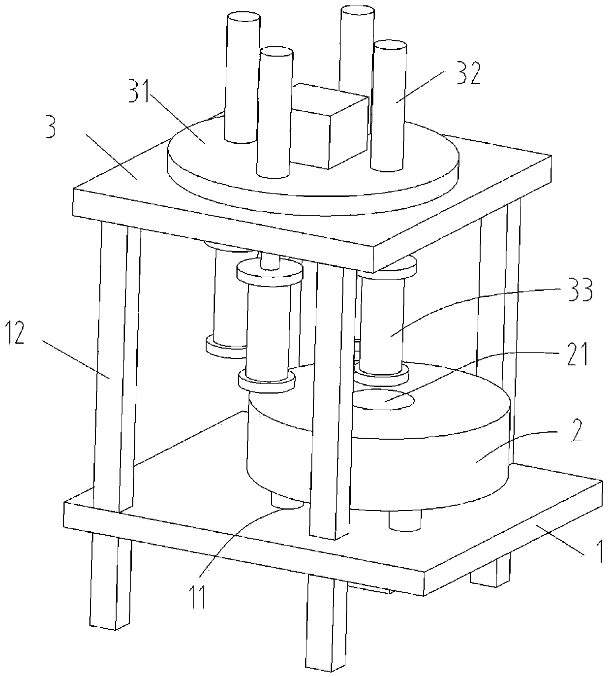
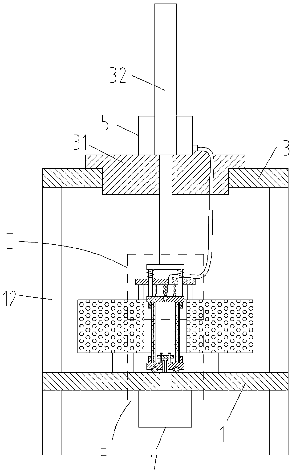
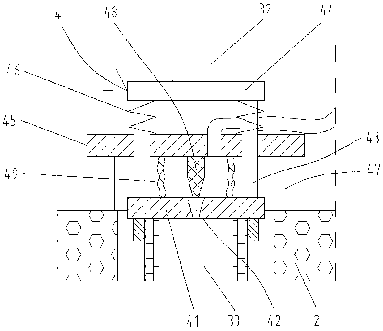
[0020] like Figure 1-6 As shown, a metal and glass encapsulation sintering furnace provided by the present invention includes a bottom plate 1, a group of support columns 11 are fixedly connected to the middle of the upper side of the bottom plate 1, and a furnace body 2 is fixedly connected to the upper side of the support columns 11. There are sintering holes 21, four connecting columns 12 are fixedly connected to the upper edge of the bottom plate 1, the upper ends of the four connecting columns 12 are fixedly connected to a support plate 3, and the middle part of the support plate 3 is rotatab...


PUM


Abstract

The invention discloses a metal and glass packaging sintering furnace. The metal and glass packaging sintering furnace comprises a bottom plate. A set of supporting columns are fixedly connected to the middle portion of the upper side of the bottom plate. The upper sides of the supporting columns are fixedly connected with a furnace body. The middle portion of the furnace body is provided with a sintering hole. The edges of the upper side of the bottom plate are fixedly connected with four connecting columns. The upper ends of the four connecting columns are fixedly connected with a supporting plate in a supporting mode. The middle portion of the supporting plate is rotatably connected with a rotary working table. The rotary working table is provided with four working positions. A telescopic cylinder is fixedly connected to each working position. Telescopic rods of the telescopic cylinders penetrate through receding holes of the rotary working table, and the lower ends of the telescopic rods are connected with furnace tubes. The lower ends of the furnace tubes are fixedly connected with a lower sealing assembly. The bottom of the bottom plate is fixedly connected with an inflation pump. The metal and glass packaging sintering furnace provided by the invention has the advantages that through multi-position design, sintering and cooling can be conducted continuously; and through reasonable use of time, the metal and glass packaging sintering furnace can meet the requirements for mass production and is high in production efficiency.

Description

technical field [0001] The invention relates to the technical field of sensor base production, in particular to a metal and glass packaging sintering furnace. Background technique [0002] When producing the sensor base, the electrode needs to be fixed in the electrode hole through the glass sleeve, and the glass sleeve and the electrode, and the glass sleeve and the electrode hole are all connected by sintering, so as to seal the metal and the glass. Sintering is carried out in a glass sintering furnace during sintering. Both ends of the furnace tube of the traditional tube-type glass sintering furnace are exposed to the outside, so that when the temperature of the furnace tube is raised, the external temperature has a particularly large impact on the furnace tube, which increases energy loss. It is not conducive to responding to the national policy of energy conservation and emission reduction. [0003] The sintering furnace in the prior art uses a single furnace tube for...

Claims


Application Information

Patent Timeline
IPC IPC(8): F27D7/06F27D9/00
CPCF27D7/06F27D9/00F27D2007/063F27D2009/0005
Inventor 郭术宝
Owner BENGBU XINGCHUANG ELECTRONICS TECH CO LTD
Learn More