Square machine base with wire conduit

A technology for conduits and bases, which is used in electromechanical devices, casings/covers/supports, electrical components, etc., can solve the problems of increased stator core weight, large stress on welds, poor firmness, etc., and achieves increased installation. The effect of span, convenient hoisting and lowering of the center of gravity

Pending Publication Date: 2019-09-17
KUNGFU SCI TECH CO LTD
View PDF0 Cites 2 Cited by
  • Summary
  • Abstract
  • Description
  • Claims
  • Application Information

AI Technical Summary

Problems solved by technology

[0002] The base of traditional generators is mostly cylindrical, which is widely used in small and medium-sized generators because of its simple structure and convenient manufacture. With the increase of generator power, the outer diameter of the base cylinder increases or the length of the base increases. , the lack of overall strength will appear; moreover, the feet of the cylindrical machine base are welded on the wall of the cylinder, the weld seam is under a lot of force, and the stator core increases with the power, which is also It will be a hidden danger; when the power increases, the outlet box will also increase, and it will become more and more difficult to fix on the circular cylinder, the firmness will be worse, and the vibration will be obvious during operation; plus medium and large Most generators require the installation of bearing temperature sensors, winding temperature sensors, and even speed sensors, etc., and the signal lines need to pass through the front and back of the base, and most of the cylindrical bases can only be routed from the outside

Method used


Image

  • Square machine base with wire conduit
  • Square machine base with wire conduit
  • Square machine base with wire conduit

Examples


Embodiment Construction

[0019] The implementation of the present invention will be described in detail below with reference to the drawings and examples, so as to fully understand and implement the implementation process of how to use technical means to solve technical problems and achieve technical effects in the present invention.

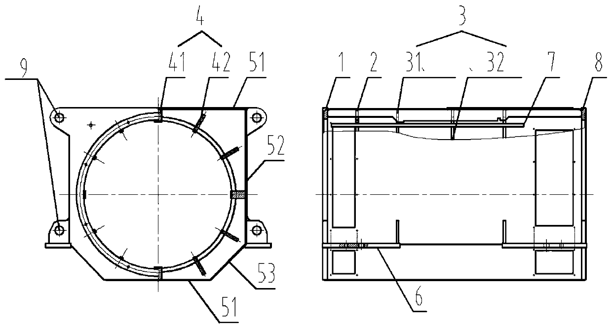
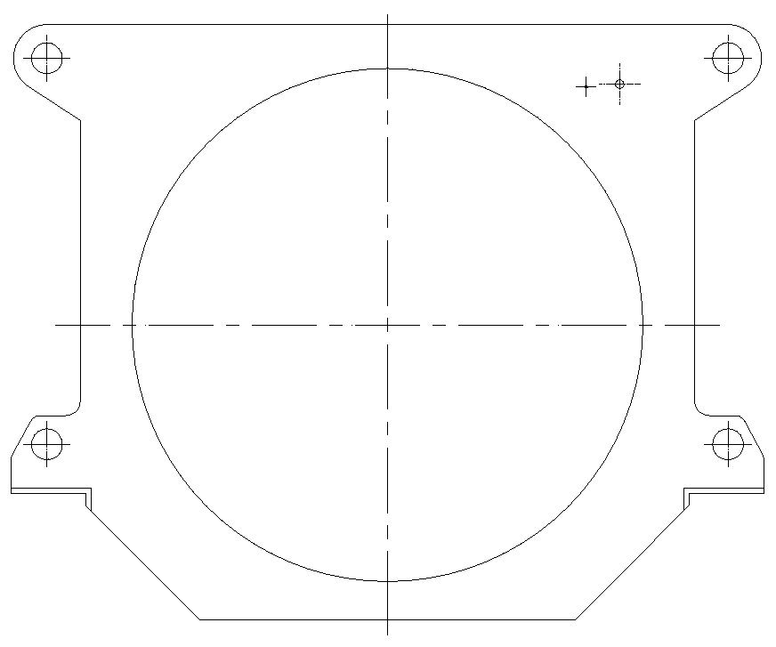
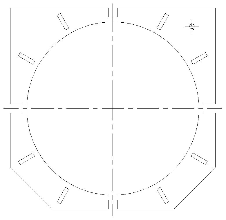
[0020] Specific embodiments of the present invention such as Figure 1 to Figure 6 As shown, a square machine base with a wire duct includes a front end plate 1, a windshield 2, a mesh base frame, a cover plate 5, a wire duct 7, a rear end plate 8 and a plurality of foot plates 6; The mesh base frame is composed of supporting plates 3 and ribs 4 interwoven. The front end plate 1 and the rear end plate 8 are respectively welded to the two ends of the mesh frame frame, and the cover plate 5 is paved and welded on the On the outer sides of the mesh base frame, the wire conduit 7 runs through the entire mesh frame frame, and a plurality of the foot plates 6 are respectively...


PUM


Abstract

The invention discloses a square machine base with a wire conduit. The square machine base comprises a front end plate, a wind shield, a net-shaped machine base framework, cover plates, the wire conduit, a rear end plate and a plurality of bottom foot plates, wherein the net-shaped machine base framework is formed by interweaving and building a supporting plate and a rib; the front end plate and the rear end plate are welded to the two ends of the net-shaped machine base framework respectively; the cover plates are paved and welded on surfaces of the outer side of the net-shaped engine base framework respectively; the wire conduit penetrates through the whole net-shaped machine base framework; the bottom foot plates are welded to the portions, extending out of the machine base, of the front end plate, the rear end plate and the supporting plate respectively; a plurality of hoisting holes are drilled in the front end plate, the rear end plate and the supporting plate; and the wind shield is arranged in the net-shaped machine base framework. According to the invention, multiple hoisting modes are provided, and hoisting is convenient; the wire conduit structure is adopted, so that various sensor signal wires can be arranged in the base, and the concealment and attractiveness are realized; and the bottom feet are raised and widened towards two sides, the center of gravity is lowered, the installation span is increased, and installation is stable and firm.

Description

technical field [0001] The invention relates to the technical field of machine bases, in particular to a square machine base with wire pipes. Background technique [0002] The base of traditional generators is mostly cylindrical, which is widely used in small and medium-sized generators because of its simple structure and convenient manufacture. With the increase of generator power, the outer diameter of the base cylinder increases or the length of the base increases. , the lack of overall strength will appear; moreover, the feet of the cylindrical machine base are welded on the wall of the cylinder, the weld seam is under a lot of force, and the stator core increases with the power, which is also It will be a hidden danger; when the power increases, the outlet box will also increase, and it will become more and more difficult to fix on the circular cylinder, the firmness will be worse, and the vibration will be obvious during operation; plus medium and large Most generator...

Claims


Application Information

Patent Timeline
Patent Type & Authority Applications(China)
IPC IPC(8): H02K5/00H02K5/22
CPCH02K5/00H02K5/225
Inventor 刘雪姣彭飞飞李寒晖
Owner KUNGFU SCI TECH CO LTD
Why Eureka
Try Eureka