
Power supply device and method of DC electric-arc furnace

A technology of DC electric arc furnace and power supply device, applied in the field of metallurgy, which can solve problems such as limited voltage regulation range, repeated oscillation of the system, overshoot of the regulation system, etc., and achieve the effect of meeting the demand of power supply current and stabilizing power energy

Inactive Publication Date: 2019-09-17
CISDI ENG CO LTD +1
View PDF6 Cites 11 Cited by
  • Summary
  • Abstract
  • Description
  • Claims
  • Application Information

AI Technical Summary

Problems solved by technology

When the output voltage is adjusted by adjusting the tap voltage of the rectifier transformer, the voltage adjustment range is limited; when the arc is stabilized by adjusting the distance between the top electrode and the bottom electrode, due to the position change of the bottom electrode during the furnace material melting process (scrap melting or molten pool fluctuations) ) and changes in the electric field strength in the furnace lead to arc current changes in the dynamic electrical characteristics of the arc. It will also exacerbate the instability of the short network system
[0004] At present, in order to improve the quality of electric arc furnace steelmaking, although a series of technologies have been developed at home and abroad to prevent the above-mentioned situation in the electric arc furnace electrode adjustment system, the effect is not ideal, and the existing electric arc furnace regulator still exists. It is adjusted by judging the changes of arc current, voltage or impedance, but it is impossible to judge the change of the actual arc column with the change of furnace conditions, which leads to the problem that the electric arc furnace regulation system cannot guarantee the stable realization of the best function for a long time

Method used


Image

  • Power supply device and method of DC electric-arc furnace
  • Power supply device and method of DC electric-arc furnace
  • Power supply device and method of DC electric-arc furnace

Examples


Embodiment Construction

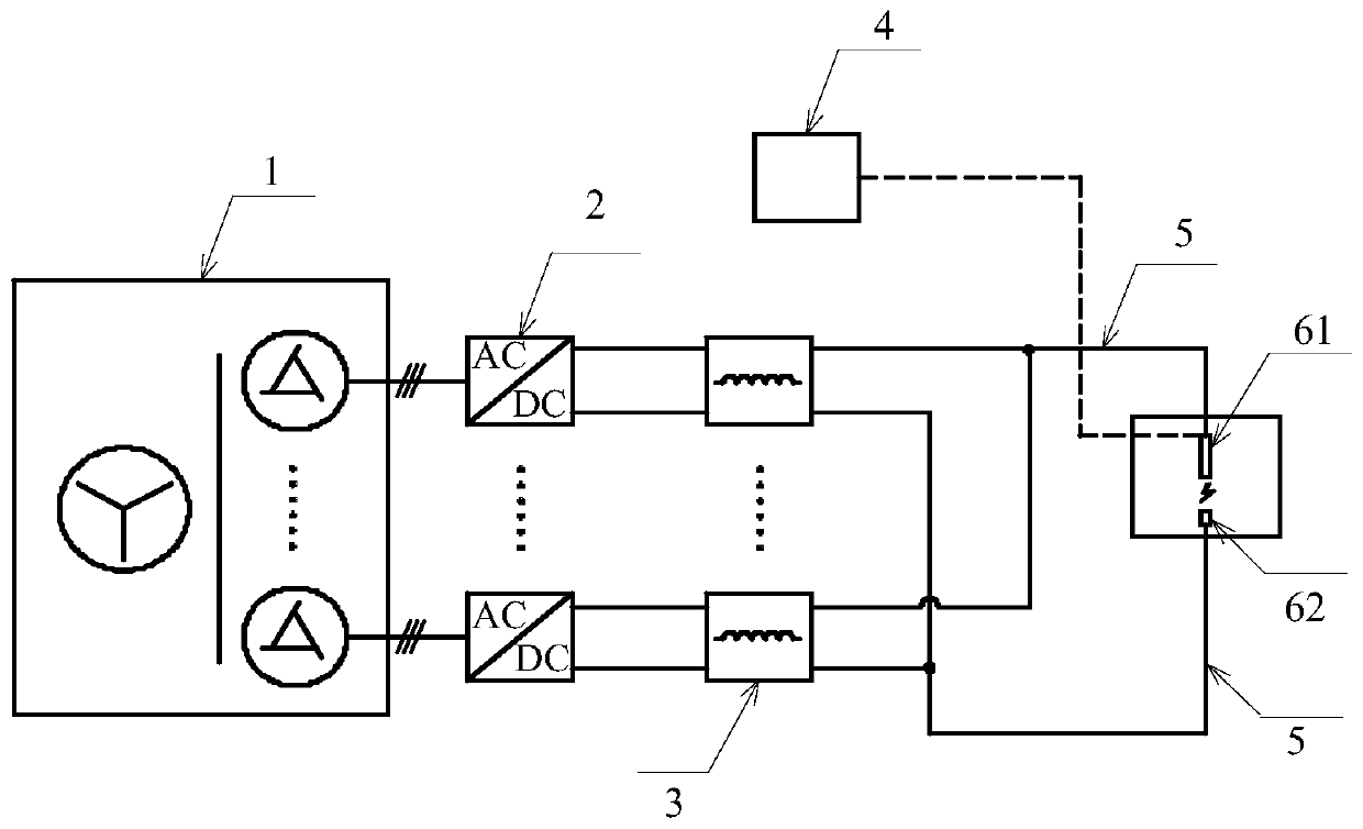
[0064] As mentioned above in the background technology, such as figure 1 As shown, the DC electric arc furnace power supply in the prior art is usually composed of a rectification phase-shifting transformer 1, a rectifier 2 and a series reactor 3, the input terminal of the rectification phase-shifting transformer 1 is connected to the power grid, and the output terminal of the rectification phase-shifting transformer 1 leads to multiple Each of the branches is connected in series with a rectifier 2 and a reactor 3 respectively, and the outputs of the multiple branches are connected in parallel to the short power supply network of the DC electric arc furnace through the confluence bus 5 to form a current output topology. A set of rectifying power supply is obtained, and the alternating current provided by the power grid is stepped down, rectified and combined to supply power for the electrode group of the direct current electric arc furnace. Wherein, the electrode group include...


PUM


Abstract

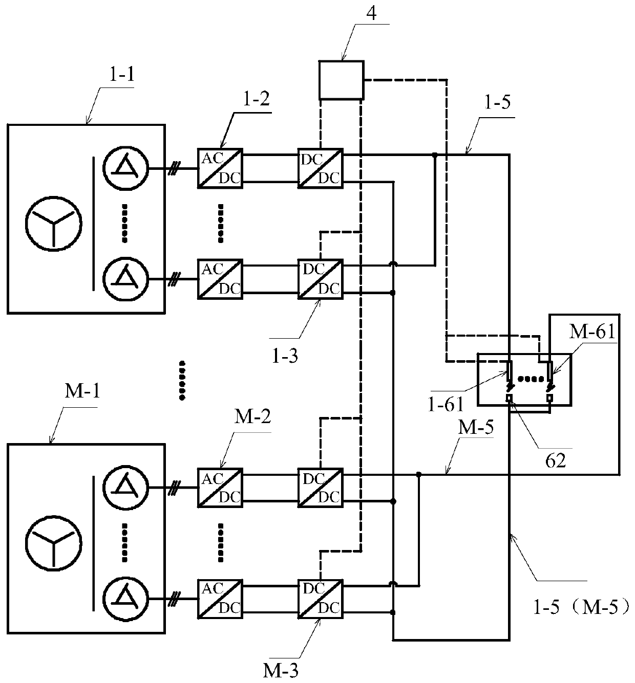
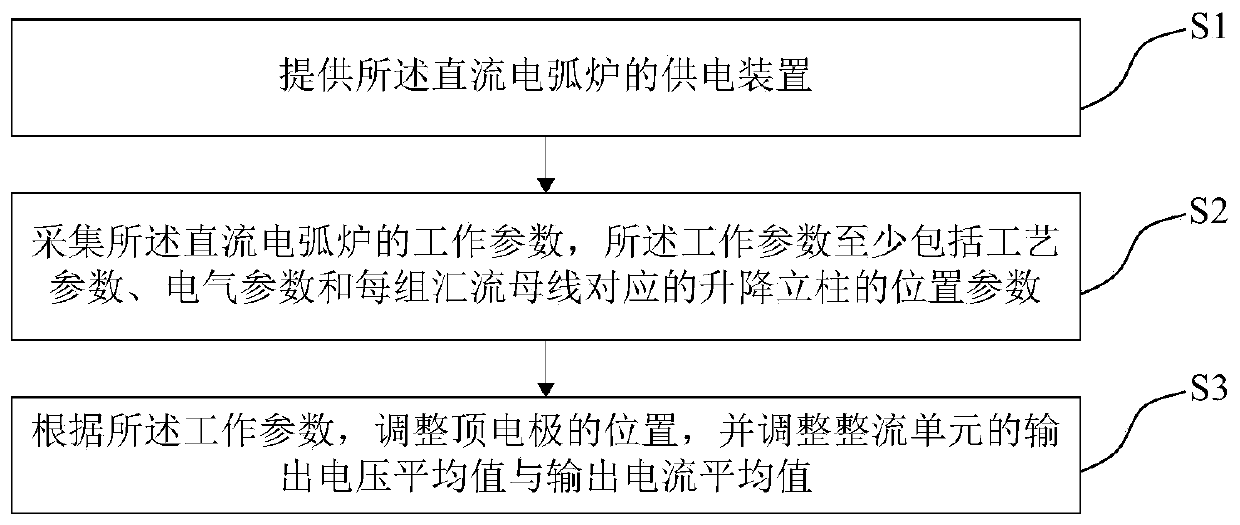
The invention provides a power supply device and a power supply method of a DC electric arc furnace. The power supply device comprises a rectification phase-shifting transformer, a rectification unit and a regulator. Through the structural design of a plurality of branches and a plurality of rectification units at the output end of the rectification phase-shifting transformer; and the outputs of the plurality of rectification units are connected in parallel and then are connected to a power supply short network of the DC electric arc furnace through a bus bar, a current output topological structure is formed, stable large current can be provided for one electrode set, power can be supplied to the multiple electrode sets through the multiple current output topological structures, and then the larger power supply current requirement of the DC electric arc furnace can be met. The regulator judges and regulates the position of the top electrode according to the real-time working parameters, so that the lifting mechanism of the top electrode can stably exert the function of stabilizing electric arc combustion for a long time. Meanwhile, the regulator regulates the output voltage and the output current of the rectifying unit according to the feedback of the real-time working parameters, and stable electric energy is provided for the DC electric arc furnace.

Description

technical field [0001] The invention relates to the technical field of metallurgy, in particular to a power supply device and a power supply method for a DC electric arc furnace. Background technique [0002] The DC power supply for DC electric arc furnace is the core equipment of DC electric arc furnace. It is usually composed of step-down transformer, rectifier device and series reactor. The arc discharge is generated by controlling the distance between the top electrode and the bottom electrode to melt the metal charge. [0003] The traditional DC electric arc furnace DC power supply provides a certain capacity of DC capacity power supply, the output voltage is adjusted by adjusting the tap voltage of the rectifier transformer, the arc is generated by adjusting the distance between the top electrode and the bottom electrode (fixed) through the electrode adjustment system, and the output current is detected Or voltage to adjust the distance between the top electrode and t...

Claims


Application Information

Patent Timeline
Patent Type & Authority Applications(China)
IPC IPC(8): H02M7/12H02M3/158F27D11/10F27D19/00
CPCH02M7/12H02M3/1584F27D11/10F27D19/00F27D2019/0028H02M1/007F27D11/00H02M1/0016H02M5/14H02M7/08H02M7/23H02J1/102F27B3/28H05B7/148H02J4/00H02J1/10H02M3/04H02M7/04
Inventor 张豫川黄其明杨宁川谈存真
Owner CISDI ENG CO LTD
Learn More