Switches for easy network connection

A switch and network cable technology, applied in the field of switches, can solve the problems of cumbersome operation, poor contact, unfavorable market promotion and use, etc., to achieve the effect of convenient plugging and unplugging process and improving stability

Inactive Publication Date: 2021-06-01
陈建新
View PDF7 Cites 1 Cited by
  • Summary
  • Abstract
  • Description
  • Claims
  • Application Information

AI Technical Summary

Problems solved by technology

[0003] The network cable jack of the traditional network switch is plugged and connected with the network cable plug. The elastic card arranged on the network cable plug cooperates with the buckle in the network cable jack. However, there are many problems in this method. The network cable jacks of the switch are very dense, and it is difficult to touch the elastic card smoothly. Sometimes, it is even directly pulled out violently, causing damage to the elastic card, making the subsequent connection extremely unstable and easy. Loose, when someone knocks over the network cable, it is easy to cause poor contact or disconnection of the network, or even damage the interface of the network switch. The operation is cumbersome, which is not conducive to marketing and use

Method used


Image

  • Switches for easy network connection
  • Switches for easy network connection
  • Switches for easy network connection

Examples


Embodiment 1

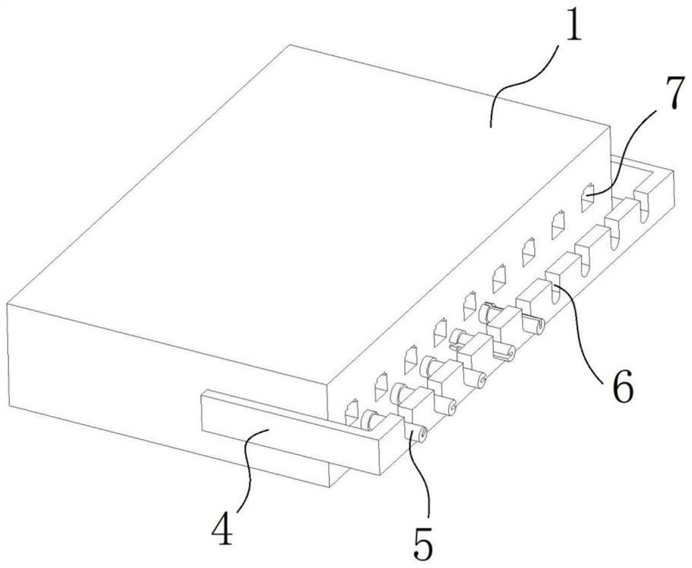
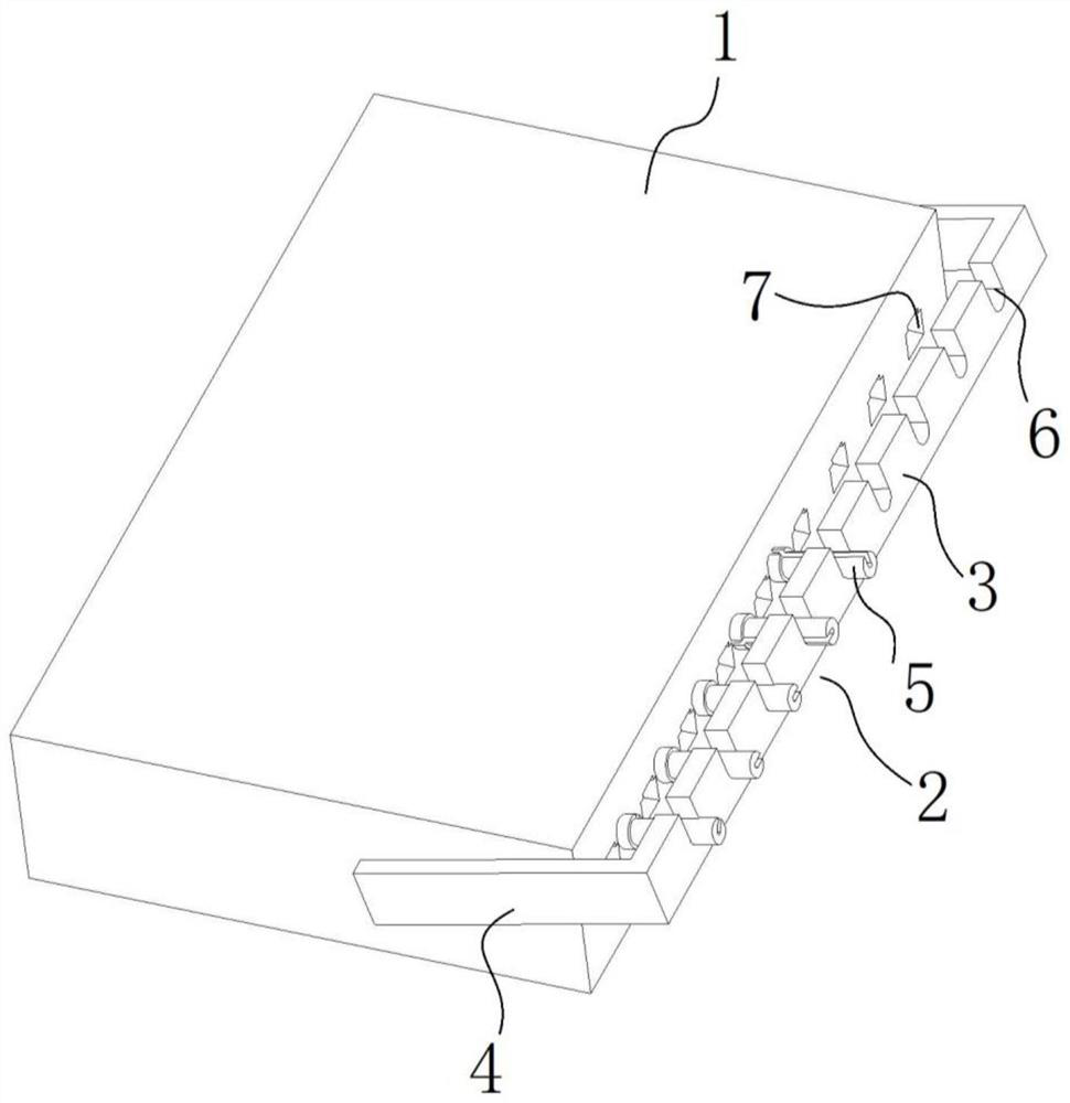
[0026] Such as figure 1 As shown, this embodiment includes a switch body 1 provided with a network cable jack 7 .

[0027] In order to improve the stability of the connection between the network cable 10 and the switch, in this embodiment, a fixing component is provided on the switch body 1 , and the fixing component is used to connect and fix the network cable 10 .

[0028] The fixed assembly includes a main frame 2 and a movable part 5, the main frame 2 is arranged on the switch body 1 on one side of the network cable jack 7, and a gap is left between the main frame 2 and the network cable jack 7. There is event space.

[0029] The main frame 2 is provided with a through slot 6 corresponding to the network cable jack 7 , and the through slot A 6 is arranged to point to the network cable jack 7 .

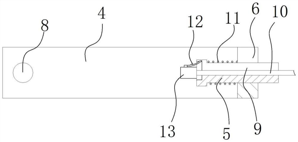
[0030] Such as Figure 5 As shown, the tail end of the movable part 5 is axially slidably fitted to the groove bottom of the through groove A 6, and the movable part 5 is axiall...

Embodiment 2

[0036]Compared with Embodiment 1, this embodiment also has the following technical features in Embodiment 2. The movable part 5 is rotatably matched with the first through slot 6, and the clamping seam is a large gap that deviates from the axis line of the second through slot 9. diameter stepped hole 14, the free end of the elastic card 12 of the network cable plug 13 extends to the side of the far center point 17 in the large diameter stepped hole 14, by rotating the movable part 5, the elastic card of the network cable plug 13 The point of contact between the free end of 12 and the large-diameter stepped hole 14 is converted from the side of the far-center point 17 to the side of the near-center point 16 .

[0037] The design of the large-diameter stepped hole 14 that deviates from the axis line of the through-groove B9 is adopted. When the network cable 10 is located at the bottom of the through-groove B9, the distance between the side wall of the large-diameter stepped hole...


PUM


Abstract

The invention belongs to the technical field of switches and provides a switch which is convenient for network cable connection. The invention comprises a switch body provided with a network cable jack, the switch body is provided with a fixed component, the fixed component includes a main frame and a movable part; There is an activity space between them. The main frame is provided with a through-slot A corresponding to the network cable jack, and the through-slot A is set to point to the network cable jack; The head end is located on one side of the network cable jack, and there is a boss on the periphery of the head end of the movable part. The movable part is detachably covered with a spring, and the two ends of the spring are respectively against the boss and the main frame. There is a through slot B for fixing the network cable to improve the stability of the connection of the network cable, and the plugging process is very convenient.

Description

technical field [0001] The invention relates to the technical field of switches, in particular to a switch that facilitates network cable connection. Background technique [0002] A network switch is a device for expanding the network, which can provide more connection ports in the sub-network to connect more computers. With the development of the communication industry and the advancement of the national economy informatization, the network switch market has shown a steady upward trend. [0003] The network cable jack of the traditional network switch is plugged and connected with the network cable plug. The elastic card arranged on the network cable plug cooperates with the buckle in the network cable jack. However, there are many problems in this method. The network cable jacks of the switch are very dense, and it is difficult to touch the elastic card smoothly. Sometimes, it is even directly pulled out violently, causing damage to the elastic card, making the subsequent...

Claims


Application Information

Patent Timeline
Patent Type & Authority Patents(China)
IPC IPC(8): H04L12/931H04Q1/02
CPCH04L49/40H04Q1/135
Inventor 陈建新刘岩王文波韩金朱德琪
Owner 陈建新
Why Eureka
Try Eureka