An intelligent light-controlled linear led lamp circuit
A technology of LED lamp circuit and light-emitting circuit, which is applied in energy-saving control technology, light source, electric light source, etc., can solve the problems of light-controlled linear LED lamp circuit that cannot meet demand, high cost, and inability to adjust brightness.
- Summary
- Abstract
- Description
- Claims
- Application Information
AI Technical Summary
Problems solved by technology
Method used
Image
Examples
Embodiment 1
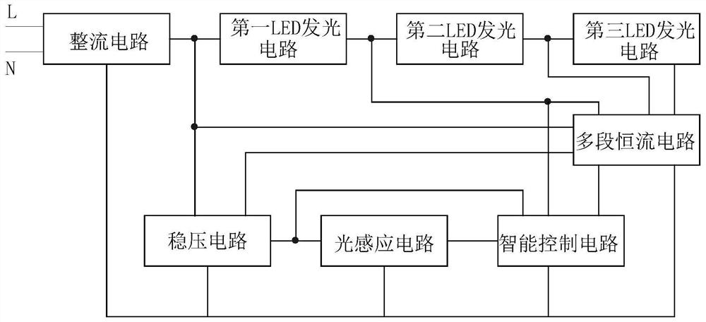
[0018] Embodiment one: if figure 2As shown, an intelligent light-controlled linear LED lamp circuit includes a rectifier circuit, a light sensing circuit, an intelligent control circuit and a first LED lighting circuit. The signal is converted into a DC voltage signal output, and the DC voltage signal output by the light sensing circuit becomes larger as the light signal intensity decreases. The intelligent light-controlled linear LED lamp circuit also includes a voltage regulator circuit, a multi-stage constant current circuit, and a second LED light-emitting circuit. and the third LED light-emitting circuit, the first LED light-emitting circuit, the second LED light-emitting circuit and the third LED light-emitting circuit are connected in series in sequence, and the first LED light-emitting circuit is connected to the DC voltage output by the rectifier circuit; The conduction voltage is recorded as V1, the conduction voltage of the second LED light-emitting circuit is reco...
Embodiment 2
[0020] Embodiment two: this embodiment is basically the same as embodiment one, the difference is as follows:
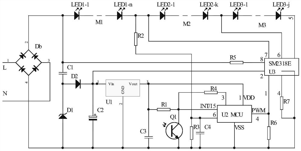
[0021] Such as image 3 As shown, in this embodiment, the voltage stabilizing circuit includes a first capacitor C1, a second capacitor C2, a third capacitor C3, a first diode D1, a second diode D2 and a first chip U1, the first chip U1 It is an LDO linear regulator chip, the first chip U1 has an input pin, an output pin and a ground pin, the second capacitor C2 is an electrolytic capacitor, the first diode D1 is a voltage regulator diode, and one end of the first capacitor C1 is a voltage regulator circuit The first input terminal of the first capacitor C1, the other end of the first capacitor C1, the cathode of the first diode D1 and the anode of the second diode D2 are connected, the cathode of the second diode D2, the anode of the second capacitor C2 and the first The input pin of a chip U1 is connected and its connecting end is the second input end of the volta...
PUM
 Abstract
Description
Claims
Application Information
 - R&D
- Intellectual Property
- Life Sciences
- Materials
- Tech Scout
- Unparalleled Data Quality
- Higher Quality Content
- 60% Fewer Hallucinations
Browse by: Latest US Patents, China's latest patents, Technical Efficacy Thesaurus, Application Domain, Technology Topic, Popular Technical Reports.
© 2025 PatSnap. All rights reserved.Legal|Privacy policy|Modern Slavery Act Transparency Statement|Sitemap|About US| Contact US: help@patsnap.com


