
Rotatable jewelry stand

A technology of ornaments and rotating blocks, applied in the field of ornaments, can solve the problems of easy accumulation of dust, inconvenient installation and power consumption of ornaments, and achieve the effects of easy viewing and taking, simple structure and convenient operation.

Active Publication Date: 2019-09-20
泉州森泸玩具有限公司
View PDF11 Cites 4 Cited by
  • Summary
  • Abstract
  • Description
  • Claims
  • Application Information

AI Technical Summary

Problems solved by technology

[0002] In the existing rotatable jewelry rack, in order to maintain the uniformity of the direction of the jewelry, the jewelry is usually hung on the jewelry, and it is inconvenient to install during the rotation of the jewelry rack. In order to improve the aesthetics of the jewelry, the lights on the jewelry rack are always on. The state of the light consumes electric energy, and the ornaments on the ornaments rack are not exposed to the outside space, making the ornaments easy to accumulate dust and inconvenient to clean. Therefore, it is necessary to further improve the ornaments rack in the prior art, thereby improving its convenience of use

Method used


Image

  • Rotatable jewelry stand
  • Rotatable jewelry stand
  • Rotatable jewelry stand

Examples


Embodiment Construction

[0015] Combine below Figure 1-6 The present invention is described in detail, for the convenience of narration, the orientations mentioned below are now stipulated as follows: the left, right, front, back, up and down directions mentioned below figure 1 The left, right, front, back, up, and down directions of the projection relationship itself are consistent.

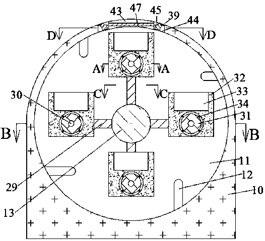
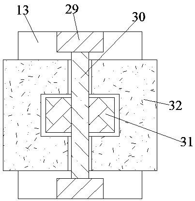
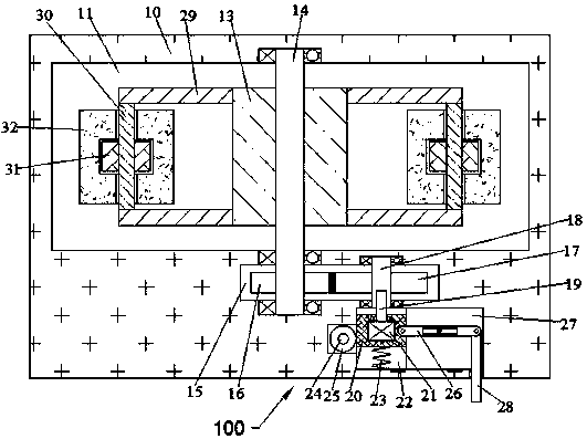
[0016] refer to Figure 1-6 , from the front, there is a frame 10 on the outside and a rotatable jewelry rack with a rotating block 13 on the inside. Block 13, a rotating device 100 is provided in the front side of the rotating chamber 11, and the front end of the rotating shaft 14 is power-connected to the rotating device 100. The outer circumference of the rotating block 13 is evenly distributed and fixed with four sets of front and rear symmetrical poles 29 , a connecting rod 30 is fixed between the poles 29, a columnar turning block 31 is fixed on the connecting rod 30, four friction support blocks 34 are evenly ...


PUM


Abstract

The invention discloses a rotatable jewelry stand. The rotatable jewelry stand comprises a frame, a rotating cavity is formed in the frame, a rotating block is rotatably arranged in the rotating cavity through a rotating shaft, a rotating device is arranged in the front side face of the rotating cavity, the front end of the rotating shaft is in power connection with the rotating device, four sets of supporting rods which are symmetric in the front-rear direction are fixedly arranged on the periphery of the rotating block in an evenly-distributed mode, connecting rods are fixedly arranged between the supporting rods, cylindrical rotary blocks are fixedly arranged on the connecting rods, four friction supporting blocks are fixedly arranged on the periphery of each rotary block in an evenly-distributed mode, and rotatable jewelry blocks are mounted on the rotary blocks in a sleeving mode. The rotatable jewelry stand is simple in structure and convenient to operate, jewelries are placed in the jewelry stand, the dust-proof effect is achieved, when the jewelries rotate to the fixing positions along with the jewelry blocks, illuminating lamps can illuminate the jewelries, enjoying and taking are convenient, in the rotating process of the jewelry blocks, the storing position of the jewelries is always kept to be upward, and stability is good.

Description

technical field [0001] The invention relates to the technical field of ornaments, in particular to a rotatable ornament stand. Background technique [0002] In the existing rotatable jewelry rack, in order to maintain the uniformity of the direction of the jewelry, the jewelry is usually hung on the jewelry, and the installation is inconvenient during the rotation of the jewelry rack. In order to improve the aesthetics of the jewelry, the lights on the jewelry rack are always on. The state of the light consumes electric energy, and the ornaments on the ornaments rack are not exposed to the outside space, making the ornaments easy to accumulate dust and inconvenient to clean. Therefore, it is necessary to further improve the ornaments rack in the prior art, thereby improving the convenience of its use . Contents of the invention [0003] The object of the present invention is to provide a rotatable ornament holder for overcoming the above-mentioned defects in the prior art...

Claims


Application Information

Patent Timeline
Patent Type & Authority Applications(China)
IPC IPC(8): A47F5/025
CPCA47F5/025
Inventor 叶吉利
Owner 泉州森泸玩具有限公司
Learn More