
A drainage device for hepatobiliary care

A technology of hepatobiliary and drainage tube, which is applied to suction devices, oil suction pumps, catheters, etc., can solve the problems of increasing the pain of patients, falling off of the drainage tube, and inconvenient movement of patients, and achieves the effect of avoiding pain, preventing falling off, and facilitating removal.

Active Publication Date: 2021-06-08
THE FIRST AFFILIATED HOSPITAL OF ZHENGZHOU UNIV
View PDF8 Cites 1 Cited by
  • Summary
  • Abstract
  • Description
  • Claims
  • Application Information

AI Technical Summary

Problems solved by technology

[0002] At present, many general surgery patients need to carry drainage devices for a long time after surgery, such as drainage bags for bile drainage and pancreatic duct drainage bags for pancreatic juice drainage. The tube falls off. In the prior art, the application number 201520167547.0 discloses a special drainage device for hepatobiliary department, which includes a tube body and a drainage bag. A conical head is provided above the tube body, and a drainage device is provided between the conical head and the tube body. The elastic supporting column on the outer circumference of the upper part, through the control line connected with the elastic supporting part, makes the elastic supporting column bend and expand, so as to prevent the tube body from falling off from the liver and gallbladder, but it cannot limit the sliding of the tube body in the liver and gallbladder. When the body is affected by external forces and slides into the liver and gallbladder, it is easy to increase the pain of the patient. In view of the shortcomings of the prior art, the present invention provides a drainage device for hepatobiliary care that can prevent the drainage tube from sliding

Method used


Image

  • A drainage device for hepatobiliary care
  • A drainage device for hepatobiliary care
  • A drainage device for hepatobiliary care

Examples


Embodiment Construction

[0019] The technical solutions in the embodiments of the present invention will be clearly and completely described below in conjunction with the accompanying drawings in the embodiments of the present invention. Obviously, the described embodiments are only some of the embodiments of the present invention, not all of them. Based on The embodiments of the present invention and all other embodiments obtained by persons of ordinary skill in the art without making creative efforts belong to the protection scope of the present invention.

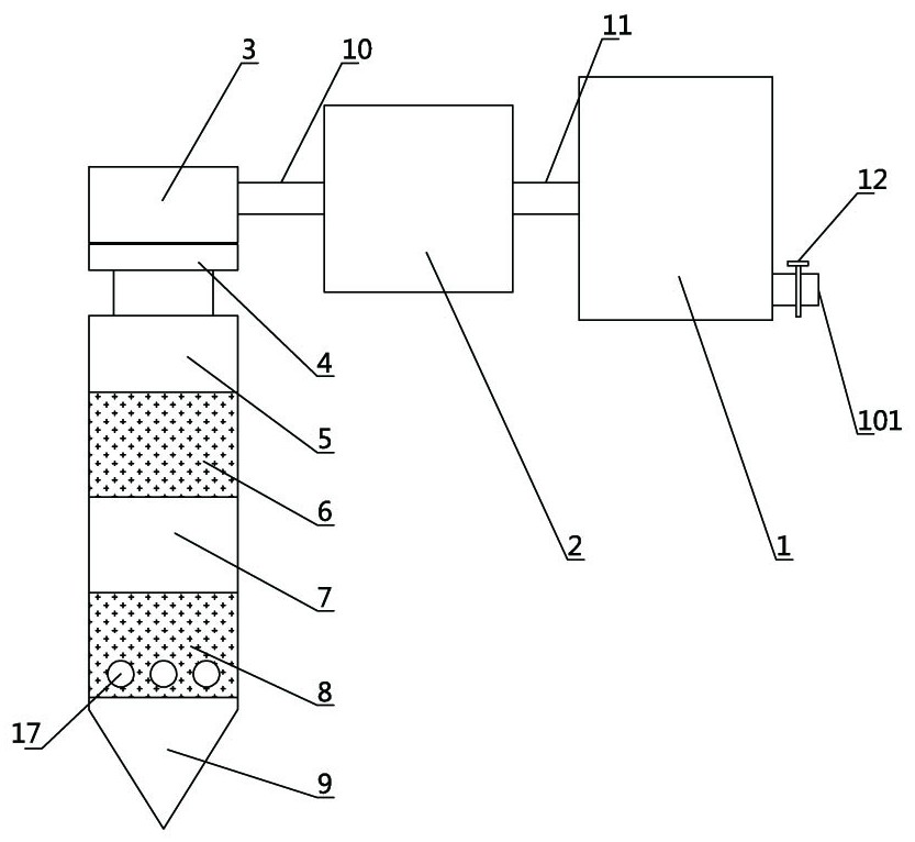
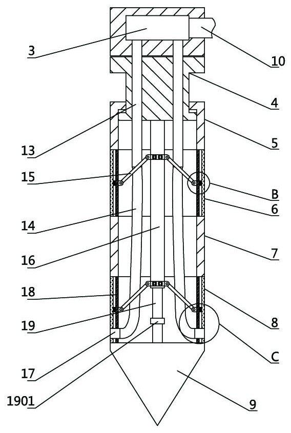
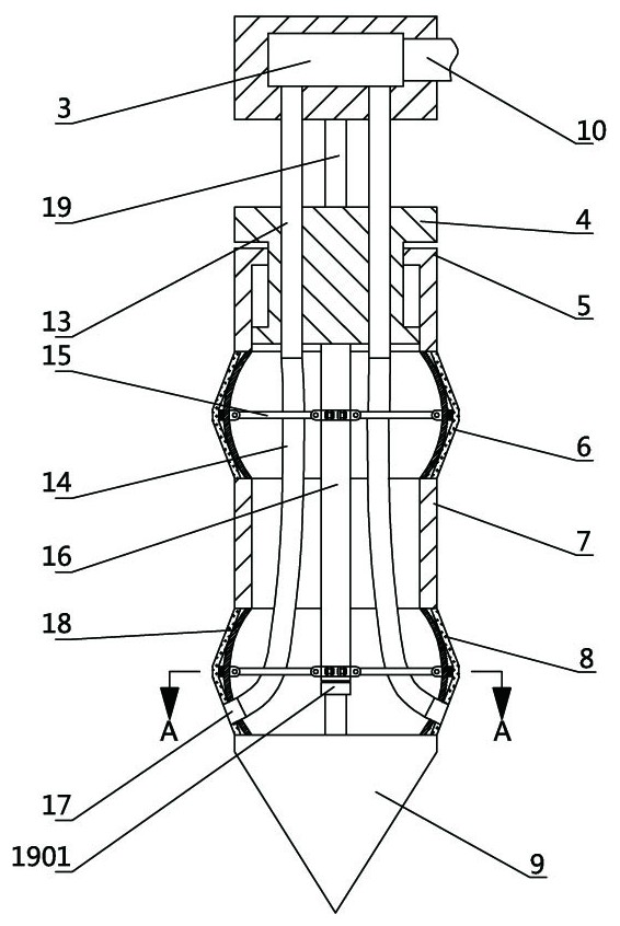
[0020] see Figure 1-6 , the present invention provides a technical solution: a drainage device for hepatobiliary care, including a liquid storage chamber 1, a drainage pump 2 and a drainage terminal, the drainage terminal includes a water collection chamber 3, a sliding ring 4, and a first cavity 5 , the first rubber sleeve 6, the second cavity 7, the second rubber sleeve 8 and the thorn cone 9, the first cavity 5, the second cavity 7, the orig...


PUM


Abstract

The invention discloses a drainage device for hepatobiliary care, which comprises a liquid storage chamber, a drainage pump and a drainage terminal. The drainage terminal comprises a water collecting chamber, a sliding ring, a first cavity, a first rubber sleeve, and a second cavity body, the second rubber sleeve and the thorn cone, after the thorn cone is inserted into the liver and gallbladder, the sliding ring is connected to the sliding cylinder, the sliding cylinder is connected to the shrapnel through the connecting rod, the sliding ring is moved, and the connecting rod is used to push the shrapnel to deform, so that the first rubber The middle part of the sleeve and the second rubber sleeve is expanded outward synchronously, and the first rubber sleeve located outside the liver gallbladder and the second rubber sleeve located inside the liver are expanded to restrict the device in two directions, which can not only prevent the device from The liver falls off, and it can prevent the device from being inserted too deeply into the liver. In addition, the two-way limitation of the first rubber sleeve and the second rubber sleeve can also prevent the device from sliding at the insertion port of the liver, and fix it firmly, preventing the device from sliding to the patient. cause pain.

Description

technical field [0001] The invention belongs to the technical field of medical equipment, in particular to a drainage device for hepatobiliary care. Background technique [0002] At present, many patients in general surgery need to carry drainage devices for a long time after surgery, such as drainage bags for bile drainage and pancreatic duct drainage bags for pancreatic juice drainage. The tube falls off. In the prior art, the application number 201520167547.0 discloses a special drainage device for hepatobiliary department, which includes a tube body and a drainage bag. A conical head is provided above the tube body, and a drainage device is provided between the conical head and the tube body. The elastic supporting column on the outer circumference of the upper part, through the control line connected with the elastic supporting part, makes the elastic supporting column bend and expand, so as to prevent the tube body from falling off from the liver and gallbladder, but i...

Claims


Application Information

Patent Timeline
Patent Type & Authority Patents(China)
IPC IPC(8): A61M1/00A61B17/34
CPCA61B17/3415A61B17/3417A61M1/80A61M1/84
Inventor 王迪王曼曼叶青敏苗莹王晶黄雪柯王潇董赛男裴红敏
Owner THE FIRST AFFILIATED HOSPITAL OF ZHENGZHOU UNIV
Learn More