Pressure-driven type anti-backflow microporous atomizing device

A technology of microporous atomization and anti-backflow, which is applied in nebulizers for treatment, other medical devices, respirators, etc., and can solve problems such as increasing the risk of infection, affecting gas pressure and flow, and failing to achieve the effect of treatment , to reduce the chance of infection, ensure the pressure and flow, and reduce the effect of liquid residue

Pending Publication Date: 2019-09-20
马利军 +2
View PDF0 Cites 4 Cited by
  • Summary
  • Abstract
  • Description
  • Claims
  • Application Information

AI Technical Summary

Problems solved by technology

[0007] (1) Condensed water generated in the pipeline during the nebulization period, cough secretions of the patient's airway, etc. are easily poured into the nebulizer, causing drug pollution and wasting drugs. At the same time, if the substances poured into the nebulizer cannot be cleaned up in time , it will form a bacterial culture medium, which is easy to breed bacteria and increase the risk of infection. The bred bacteria will enter the patient's respiratory tract with the next atomization, causing ventilator-associated pneumonia (VAP) in severe cases, increasing the length of hospital stay and increasing the patient's financial difficulties , increased mortality
[0008] (2) Patients generally use a semi-sitting position when nebulizing, but mechanically ventilated patients often adopt lying positions, 30-degree sitting positions, side lying positions, etc. due to their critical condition and cannot meet the requirements. When changing, it is easy to cause the inclination of the atomizer, and the pressure gas used in the atomization of the existing atomizer usually enters from the lower end of the atomizer. Once the atomizer is tilted, the liquid level in the atomizer will decrease. Tilting occurs, causing the part of the liquid medicine to not be fully atomized, and part of th...

Method used


Image

  • Pressure-driven type anti-backflow microporous atomizing device
  • Pressure-driven type anti-backflow microporous atomizing device
  • Pressure-driven type anti-backflow microporous atomizing device

Examples


Embodiment 1

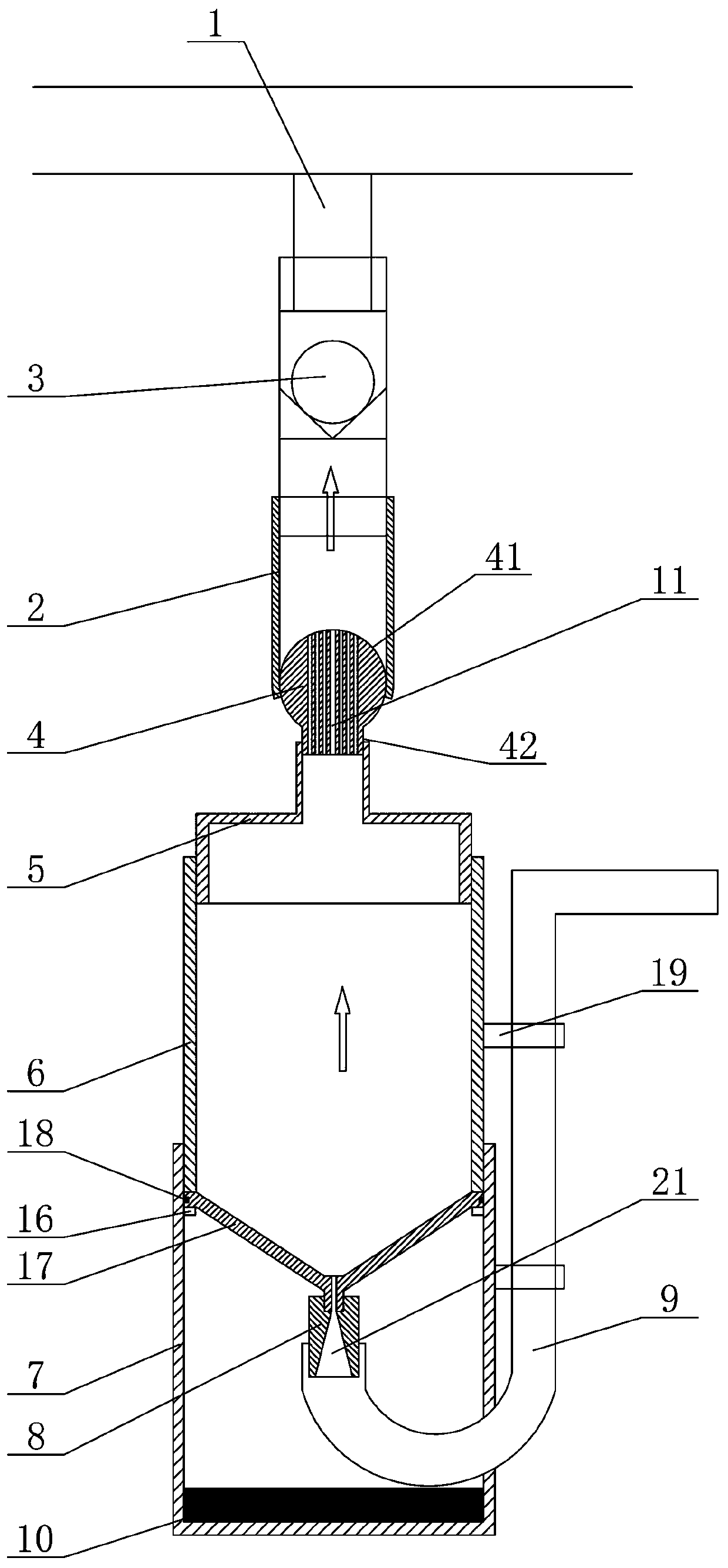
[0043] Such as figure 1 As shown, a pressure-driven anti-backflow microporous atomization device includes an upper joint 1, an upper connecting pipe 2, a one-way valve 3, a hinged ball 4, an upper end cap 5, an atomization chamber 6, a lower end cap 7, an air inlet Joint 8, intake pipe 9 and counterweight 10, the upper joint 1 is a T-shaped three-way joint, including two horizontally connected interfaces and one vertical port, the two horizontally connected The interface is respectively connected to the ventilator and the artificial airway or the mask through the pipeline, the vertical port of the upper joint 1 is connected to the upper connecting pipe 2, and the upper end of the upper connecting pipe 2 is connected to the vertical port of the upper joint 1, and the upper The lower end of the connecting pipe 2 is connected to the hinged ball 4. The upper connecting pipe 2 is provided with a one-way valve 3. The hinged ball 4 includes a ball head 41 and a lower connecting porti...

Embodiment 2

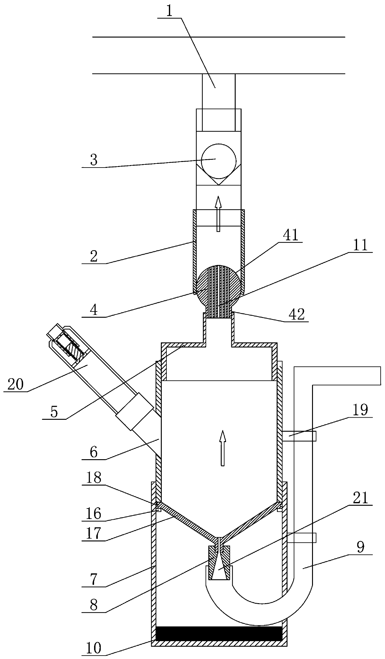
[0049] Such as figure 2 , Figure 5 As shown, Example 1 is repeated, with the following differences: the atomization chamber 6 is provided with a liquid inlet device 20, and the liquid inlet device 20 is arranged on one side of the atomization chamber 6, and the liquid inlet device 20 includes Liquid inlet pipe 201, piston device 202, sealing ring 203, spring 204 and spring seat 205, described liquid inlet pipe 201 comprises large-diameter pipe body section 207 and small-diameter nozzle section 206, and one end of nozzle section 206 is used for connecting In the syringe, the other end of the nozzle section 206 is screwed and fastened to one end of the tube body section 207, and the other end of the tube body section 207 is connected to the atomization chamber 6 and communicates with the inner cavity of the atomization chamber 6. The tube The body part 207 is provided with a spring seat 205, the spring seat 205 includes a seat plate and a sliding post of an integral structure...

Embodiment 3

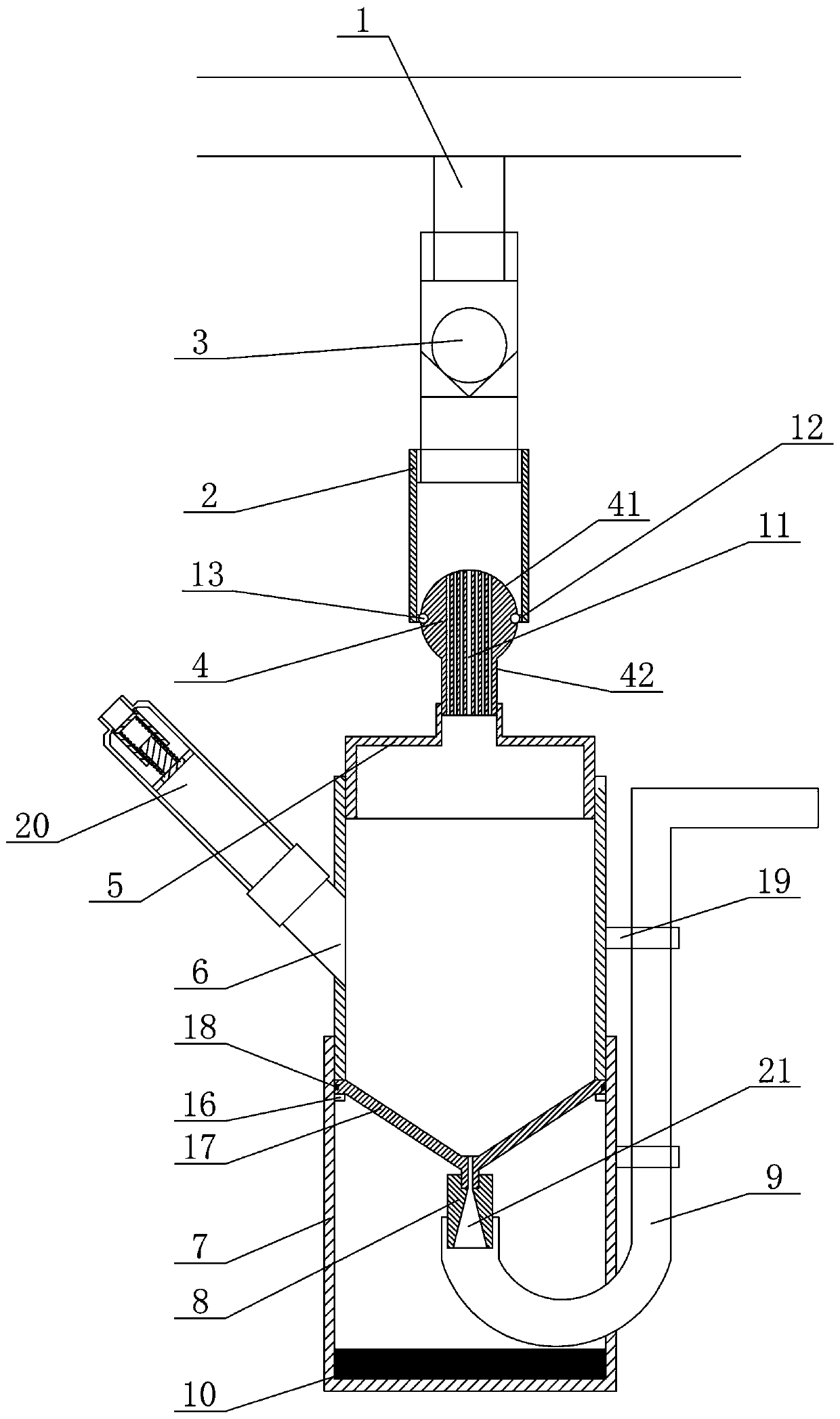
[0052] Such as image 3 , Figure 5 As shown, the second embodiment is repeated, with the following differences: blind holes 12 are symmetrically arranged on both sides of the ball head 41 of the hinged ball 4, and pin shafts are symmetrically arranged in the lower opening of the upper connecting pipe 2 13. The pin shaft 13 corresponds to the blind hole 12, and the pin shaft 13 is inserted into the blind hole 12, and the hinge ball 4 rotates relative to the upper connecting pipe 2 with the pin shaft 13 as the rotation axis. In this embodiment, the hinged ball 4 deflects and swings around the pin shaft 13 .


PUM


Abstract

The invention relates to a pressure-driven type anti-backflow microporous atomizing device. The pressure-driven type anti-backflow microporous atomizing device comprises an upper joint, an upper connecting pipe, a one-way valve, a hinged ball, an upper end cover, an atomizing chamber, a lower end cover, an air inlet joint, an air inlet pipe and a counterweight block. The upper joint is a T-shaped three-way joint which comprises two horizontally communicated connectors and a vertical connector. The two horizontally communicated connectors of the upper joint are respectively connected with a respirator and an artificial airway through pipelines; the vertical connector of the upper joint communicates with the upper connecting pipe, and the upper end of the upper connecting pipe is connected with the vertical connector of the upper joint; the lower end of the upper connecting pipe is connected with the hinged ball, and the one-way valve is arranged in the upper connecting pipe; and the one-way valve can prevent backflow of condensate water generated in the pipelines, cough secretions of an airway of a patient and the like. The probability of infection can be effectively reduced, and a ball hinge structure is matched with the counterweight. Therefore, when the body position of the patient changes, it ensures that the atomizing device is in a vertical state all the time, the atomized liquid medicine is kept at the lowest position of the atomizing device all the time, so that the liquid medicine residue is reduced, and the atomization effect is ensured.

Description

[0001] Technical field: [0002] The invention belongs to the technical field of medical auxiliary equipment, and in particular relates to a pressure-driven anti-backflow microporous atomization device used for the atomization treatment of patients assisted by a ventilator. [0003] Background technique: [0004] At present, in clinical practice, especially in intensive care units, there are more and more occasions where ventilators are used to help patients breathe. In addition to assisting breathing, ventilators can also be used for nebulization of medicines. In addition to intravenous medication, many special pulmonary infections must also be treated with local atomized inhalation, because local atomized inhalation has a better effect of eliminating phlegm and expectoration. [0005] At present, when performing nebulization therapy on ventilator patients clinically, a T-shaped three-way connector is usually provided. One of the two horizontally connected connectors of the T-...

Claims


Application Information

Patent Timeline
IPC IPC(8): A61M11/02A61M11/00A61M39/10A61M39/24A61M16/00
CPCA61M11/003A61M11/02A61M16/0003A61M39/105A61M39/24
Inventor 马利军高胜浩程剑剑忽新刚刘红梅王海播
Owner 马利军
Why Eureka
Try Eureka