Safety anti-drop device for power transmission line climbing pole operation
A technology for power transmission lines and boarding poles, which is applied to safety belts, life-saving equipment, etc., and can solve problems such as no safety protection ropes
- Summary
- Abstract
- Description
- Claims
- Application Information
AI Technical Summary
Problems solved by technology
Method used
Image
Examples
Embodiment 1
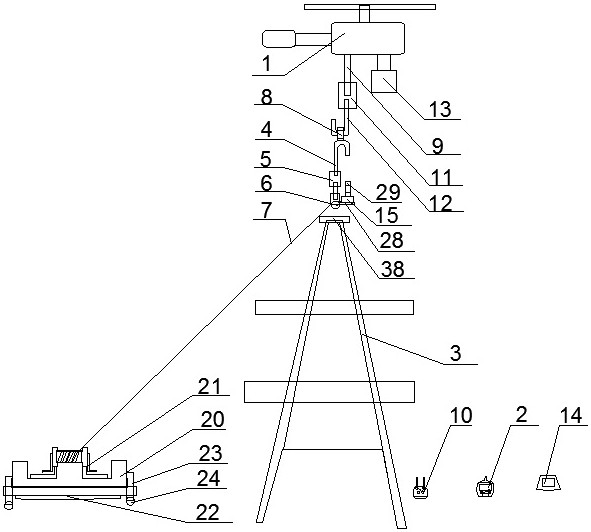
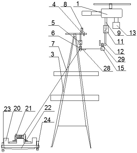
[0038] like figure 1 , 2As shown, a safety anti-drop device for power transmission line boarding pole operation includes a rotor UAV 1, a UAV remote controller 2, a fixing module for fixing the hook fixed point 38 on the iron tower 3 and being arranged on the rotor without Auxiliary module at the lower end of HMI 1;
[0039] like figure 1 , 2 As shown, the fixed module includes a fixed hook 4, a universal joint 5 arranged at the lower end of the fixed hook 4, a pulley 6 connected to the universal joint 5 and a traction rope 7 arranged in the pulley 6, the fixed hook 4 A first shackle 8 is also arranged on the top; the upper end of the universal joint 5 is welded together with the lower end of the fixed hook 4, and the lower end of the universal joint 5 is welded together with the upper end of the pulley 6;
[0040] like figure 1 , 2 As shown, one end of the traction rope 7 is connected to the retractable module arranged on the ground, the other end of the traction rope 7...
Embodiment 2
[0068] The difference between the present embodiment and the first embodiment is that the connecting hook 12 is used to directly hook the second shackle 29 arranged on the cover body, and the traction rope 7 is erected on the pole tower, that is, there is no fixed hook 4 on the traction rope 7 , pulley 6, but make the traction rope 7 directly set up on the cross arm of the pole tower or other hook fixed points 38.
[0069] Especially, when people are constructing on the utility poles with a relatively simple structure of the power transmission line, it seems a bit cumbersome to set components such as the fixing hook 4 and the like.
Embodiment 3
[0071] like Figure 8 As shown, the difference between this embodiment and Embodiment 1 is that the pulley 6 is also provided with a protection module for preventing the traction rope from breaking away from the groove body of the pulley, and the protection module includes a limit plate 30 arranged in the pulley, a set The tightening bolt 31 on the limiting plate, the anti-slip sleeve 32 arranged on the upper end of the tightening bolt and the tightening nut 33 arranged on the tightening bolt 31 and located at the lower end of the limiting plate 30 .
[0072] Before the cover body 15 passes through the pulley 6, the tightening bolt 31 is screwed upwards, and the stop plate 30 and the tightening nut 33 are driven to move upward; Twist and tighten bolt 31, drive stop plate 30 and tighten nut 33 to move downwards, make the distance between limit plate and the pulley less than the sectional diameter of traction rope 7, even traction rope can't directly disengage from pulley.
[0...
PUM
 Abstract
Description
Claims
Application Information
 - R&D
- Intellectual Property
- Life Sciences
- Materials
- Tech Scout
- Unparalleled Data Quality
- Higher Quality Content
- 60% Fewer Hallucinations
Browse by: Latest US Patents, China's latest patents, Technical Efficacy Thesaurus, Application Domain, Technology Topic, Popular Technical Reports.
© 2025 PatSnap. All rights reserved.Legal|Privacy policy|Modern Slavery Act Transparency Statement|Sitemap|About US| Contact US: help@patsnap.com


