Welding ring press-fitting machine

A press-fitting machine and welding ring technology, applied in metal processing, metal processing equipment, manufacturing tools, etc., can solve the problem that the production efficiency of welding ring assembly cannot be guaranteed, there is no detection, rejection or swing, and the welding ring press-fitting effect is poor, etc. problem, to achieve the effect of good pressing effect, reduce cost and trouble, and improve production efficiency

Pending Publication Date: 2019-09-20
俞才王
View PDF1 Cites 0 Cited by
  • Summary
  • Abstract
  • Description
  • Claims
  • Application Information

AI Technical Summary

Problems solved by technology

[0004] The above scheme solves the problem of low automation of welding ring pressing process or welding ring pressing mechanism and poor welding ring pressing effect to a certain extent, but there are still many deficiencies in this scheme, for example, the described process and design The mechanism does not have a series of structures such as detection, rejection or plate placement, which cannot guarantee that the production efficiency of welding ring assembly will be improved

Method used


Image

  • Welding ring press-fitting machine
  • Welding ring press-fitting machine
  • Welding ring press-fitting machine

Examples


Embodiment Construction

[0026] The present invention will be described in further detail below with reference to the accompanying drawings and specific embodiments.

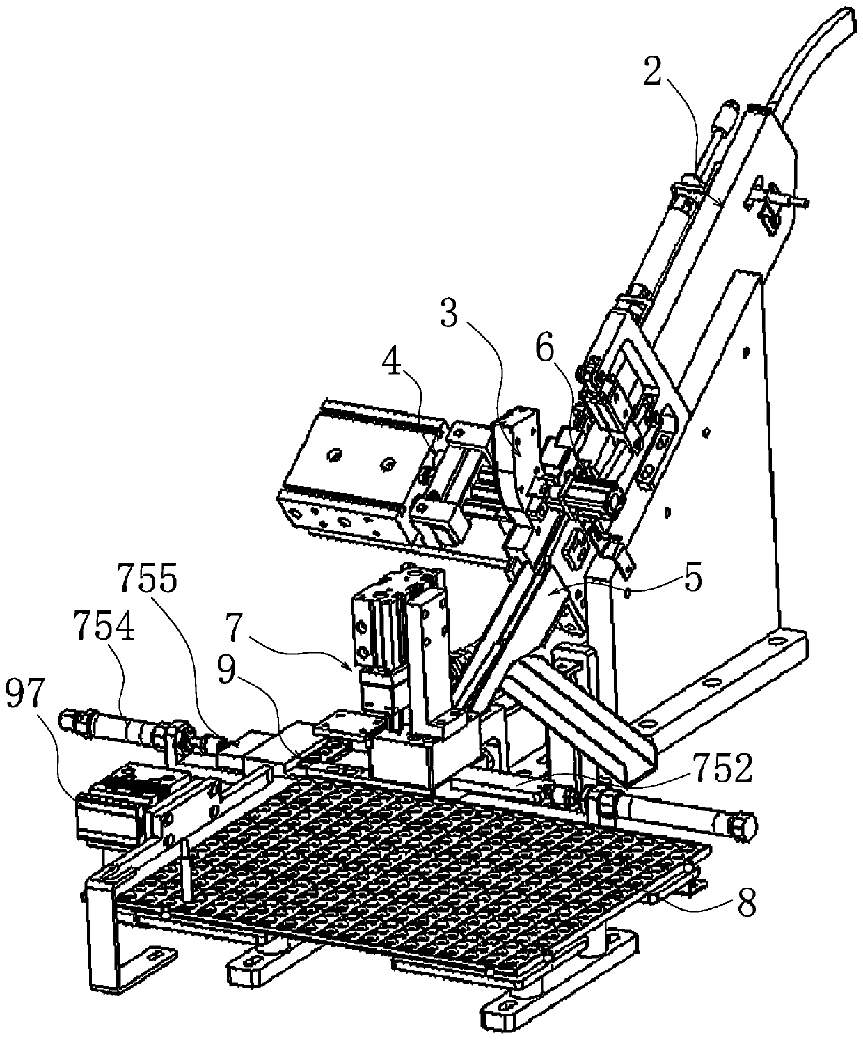
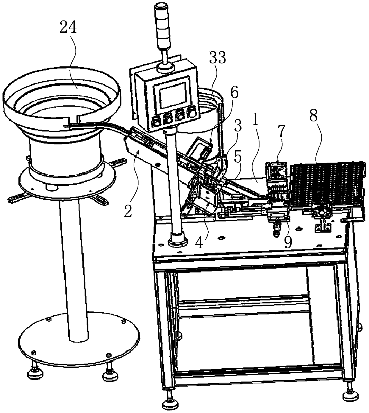
[0027] like Figure 1-8 As shown in the figure, the welding ring pressing machine includes a horizontally arranged platen 1, and a valve seat conveying mechanism 2 arranged obliquely and used for conveying the valve seat body is arranged on the platen 1. The valve seat conveying mechanism 2 is located at the lower end and is It is communicated with the welding ring conveying mechanism 3 for conveying the welding ring body, and between the valve seat conveying mechanism 2 and the welding ring conveying mechanism 3, there is a welding ring assembly mechanism 4 for assembling the welding ring body on the valve seat body. The lower end of the conveying mechanism 2 is connected with an inclined discharge conveying channel 5, and one end of the valve seat conveying mechanism 2 close to the discharging conveying channel 5 is provided with a va...


PUM


Abstract

The invention provides a welding ring press-fitting machine. The welding ring press-fitting machine solves the problems that an existing welding ring press-fitting machine is low in automation degree, and poor in the press-fitting effect. The welding ring press-fitting machine comprises a horizontally-arranged table plate, a valve seat conveying mechanism is arranged on the table plate, the lower end of the valve seat conveying mechanism communicates with a welding ring conveying mechanism, a welding ring assembling mechanism is arranged between the valve seat conveying mechanism and the welding ring conveying mechanism, a discharging conveying channel which is obliquely arranged is connected to the end, located below the valve seat conveying mechanism, of the valve seat conveying mechanism, the end, close to the discharging conveying channel, of the valve seat conveying mechanism is provided with a valve seat overturning mechanism capable of overturning a valve seat body assembled with a welding ring body, one end of the discharging conveying channel is connected with a valve seat detecting mechanism, a discharging plate is positioned on the side, of the valve seat detecting mechanism, on the table plate, and a disc arranging mechanism capable of sequentially placing the valve seat body assembled with the welding ring body on the table board is arranged on the table board. The welding ring press-fitting machine has the advantages of being high in automation degree, good in press-fitting effect, good in detection, good in disc arranging effect and the like.

Description

technical field [0001] The invention belongs to the technical field of mechanical automation equipment, and particularly relates to a welding ring pressing machine. Background technique [0002] The welding ring is a welding tool. The valve seat is a detachable surface part in the valve, which is used to support the fully closed position of the valve core and form a sealing pair. Generally, the seat diameter is the maximum flow diameter of the valve. Generally speaking, the valve seat and the valve core belong to the same valve assembly, and there are often several through holes on the valve core. When the valve core is installed on the valve seat, the installation angle of the valve core is set, so it is necessary to install the valve core. To find out, if the welding ring is assembled on the valve seat, the assembly of the valve seat and the valve core will become easier. When the welding ring is assembled into the valve seat, the welding Press the ring into the seat. A...

Claims


Application Information

Patent Timeline
Patent Type & Authority Applications(China)
IPC IPC(8): B23P19/027B23P19/04B23P19/00
CPCB23P19/00B23P19/001B23P19/027B23P19/04
Inventor 俞才王
Owner 俞才王
Why Eureka
Try Eureka