Control method for forced current cathodic protection of storage tank

A technology of forced current and cathodic protection, which is applied in the field of cathodic protection and anticorrosion, can solve the problems of abnormal output, the inability of the potentiostat to automatically identify interference, and the inability to accurately achieve the effect of cathodic protection.

Active Publication Date: 2019-09-20
QINGDAO YAHE SCI & TECH DEV
View PDF7 Cites 2 Cited by
  • Summary
  • Abstract
  • Description
  • Claims
  • Application Information

AI Technical Summary

Problems solved by technology

However, in this operation mode, when there is stray current in the environment, the IR will change greatly, and the potentiostat cannot automatically identify the interference, and the output may be abnormal and the phenomenon of automa

Method used


Image

  • Control method for forced current cathodic protection of storage tank
  • Control method for forced current cathodic protection of storage tank
  • Control method for forced current cathodic protection of storage tank

Examples


Embodiment Construction

[0079] In the following, the present invention will be specifically described through exemplary embodiments. It should be understood, however, that elements, structures and characteristics of one embodiment may be beneficially incorporated in other embodiments without further recitation.

[0080] In the description of the present invention, it should be noted that the orientation or positional relationship indicated by the terms "inner", "outer", "upper", "lower", "front", "rear" etc. are based on the The positional relationship is only for the convenience of describing the present invention and simplifying the description, but does not indicate or imply that the referred device or element must have a specific orientation, be constructed and operated in a specific orientation, and thus should not be construed as limiting the present invention. In addition, the terms "first", "second", and "third" are used for descriptive purposes only, and should not be construed as indicating...


PUM


Abstract

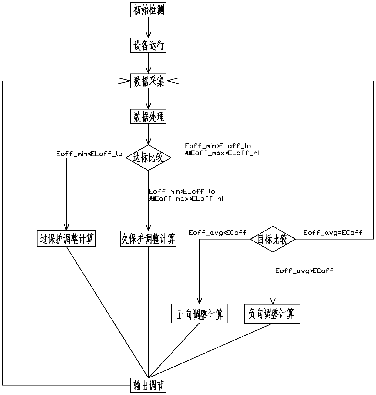
The invention discloses a control method for forced current cathodic protection of a storage tank. The control method comprises the following steps of initial detection, equipment operation, data acquisition, data process, standard reaching comparison, target comparison, over-protection adjustment and calculation, under-protection adjustment and calculation, positive adjustment and calculation, negative adjustment and calculation and output adjustment. According to the control method, the potential measured by a reference electrode when a potentiostat is powered off is the power-off potential, so that the problem that the power-off potential cannot be detected due to the fact that a polarization test piece or a polarization probe cannot be set is solved; and the output of the potentiostat is adjusted by taking the power-off potential as a control basis, the requirements of industry standards can be met, and the cathodic protection effect can be accurately achieved.

Description

technical field [0001] The invention belongs to the technical field of cathodic protection and anticorrosion, and in particular relates to a control method for forced current cathodic protection of a storage tank. Background technique [0002] The outer side of the tank bottom plate is in direct contact with the asphalt sand, but when the outer edge plate of the tank bottom is tilted, a large gap will be formed between the edge plate and the base. Due to the undulating deformation of the tank bottom plate, a There are many channels and spaces, so that rainwater can enter the center of the tank bottom plate, and the entry of rainwater will cause oxygen concentration corrosion, resulting in corrosion of the tank bottom plate. In order to solve this problem, waterproof measures have been taken on the outer edge of the bottom plate of the storage tank, but it is still difficult to solve the problem of corrosion on the bottom plate of the tank. [0003] Cathodic protection is an...

Claims


Application Information

Patent Timeline
IPC IPC(8): C23F13/04C23F13/22
CPCC23F13/04C23F13/22
Inventor 高桂飞李慧玲孔德生李长安张胜国彭明利卢少同姜刚李彦刚朱桂伟刘珂吕晓波刘科姜奉杰郑朋磊李琛付春辉孙作辉孙勤
Owner QINGDAO YAHE SCI & TECH DEV
Why Eureka
Try Eureka