A device for directional collection of spun fibers

A collecting device and spinning fiber technology, which is applied in the direction of clustering of newly extruded silk, fiber treatment, textiles and papermaking, etc., can solve the problems of poor collection effect and weak guidance, and achieve strong guidance and good collection effect , improve the collection effect

Active Publication Date: 2020-10-30
WUHAN TEXTILE UNIV
View PDF1 Cites 0 Cited by
  • Summary
  • Abstract
  • Description
  • Claims
  • Application Information

AI Technical Summary

Problems solved by technology

[0006] The purpose of the present invention is to overcome the defects and problems of weak guiding and poor collecting effect existing in the prior art, and provide a directional collecting device for spun fibers with strong guiding and good collecting effect

Method used


Image

  • A device for directional collection of spun fibers
  • A device for directional collection of spun fibers
  • A device for directional collection of spun fibers

Examples


Embodiment 1

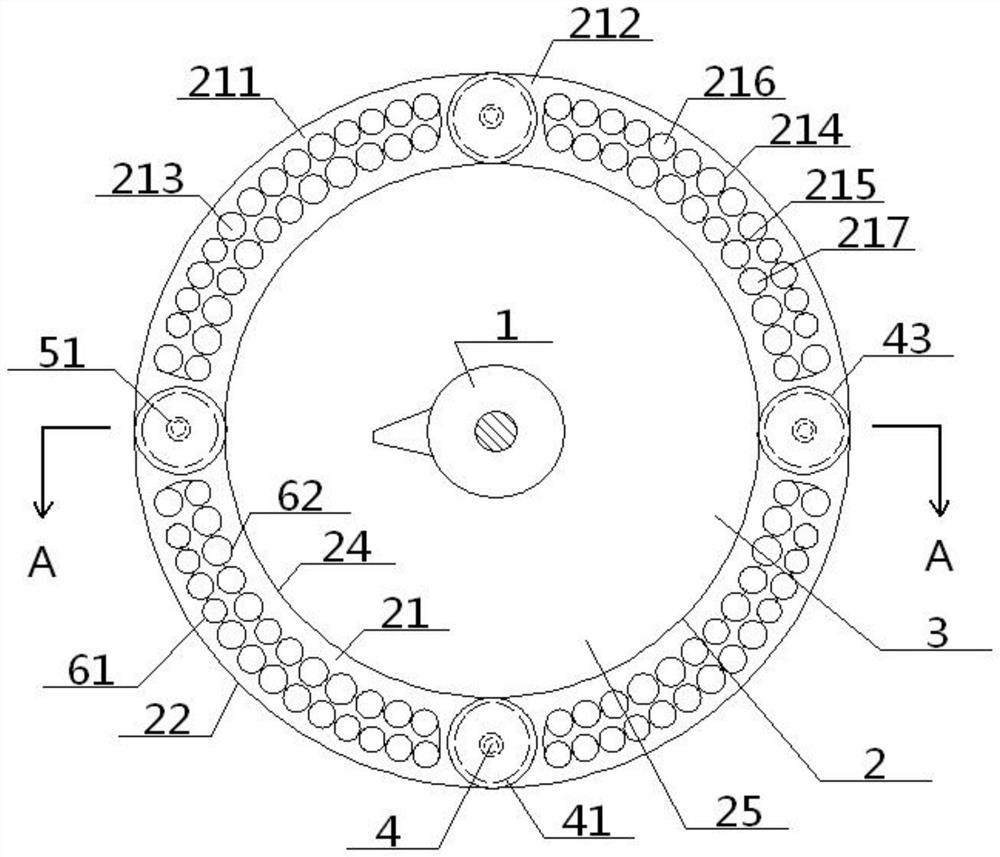
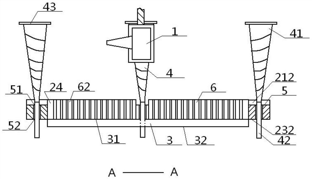
[0047] see Figure 1 to Figure 5 , a directional collection device for spun fibers; the directional collection device includes a ventilation ring disk 2, a bottom concave disk 3 and four collection rods 4, and the ventilation ring disk 2 includes a top ring disk surface 21 connected in sequence, an outer ring Wall 22, bottom ring surface 23, and inner ring wall 24, the top ring surface 21 and bottom ring surface 23 are arranged parallel up and down, the outer ring wall 22 and the inner ring wall 24 are arranged concentrically, and the inner ring wall 24 encloses an inner ring disk Cavity 25, a spinning head 1 is arranged directly above the inner ring disc cavity 25; four top arc surface areas 211 evenly arranged along the same circumference are arranged on the top ring disc surface 21, and the adjacent top arc surface areas 211 is sandwiched between a top surface area 212, and each top arc surface area 211 is provided with a plurality of top air holes 213, and the bottom ring ...

Embodiment 2

[0049] Basic content is the same as embodiment 1, the difference is:

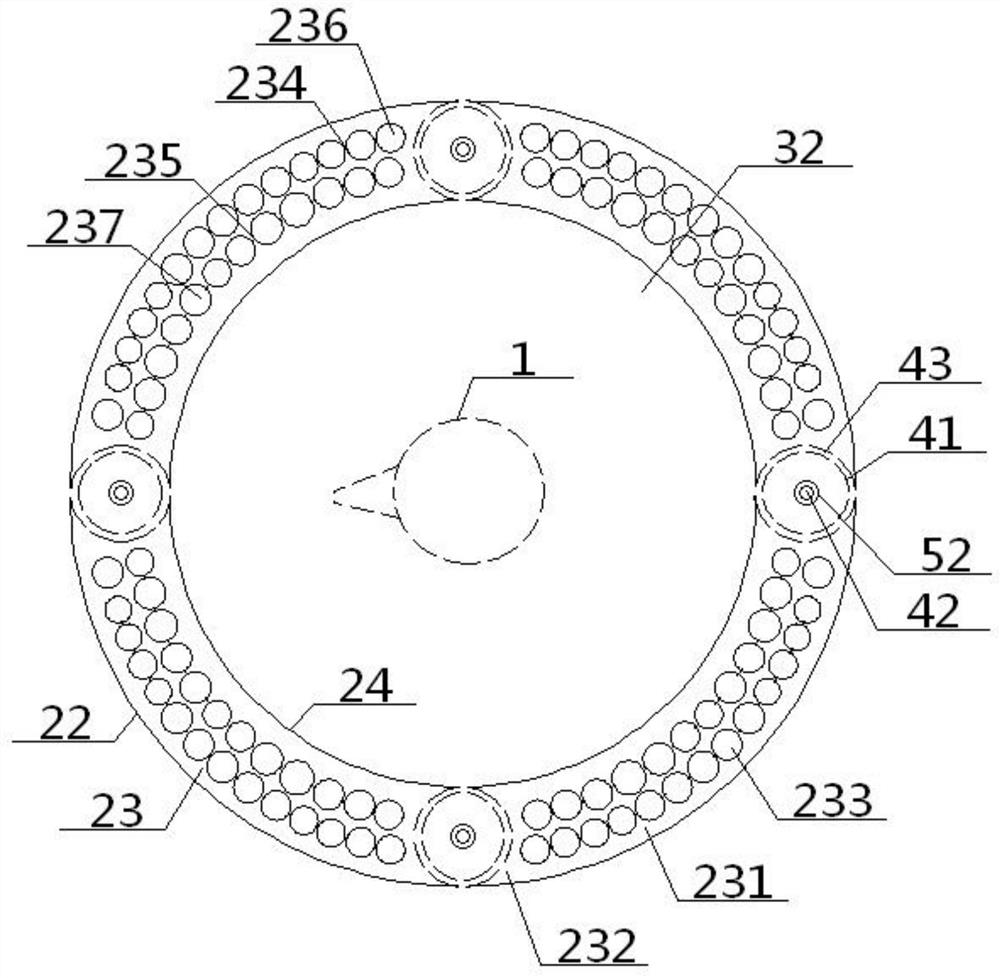
[0050] The top arc area 211 includes a concentric top outer arc area 214 and a top inner arc area 215, a plurality of top outer air holes 216 are arranged in the top outer arc area 214, and a plurality of top inner air holes are arranged in the top inner arc area 215 217, the top outer air hole 216 and the top inner air hole 217 form the top air hole 213; the bottom arc area 231 includes a concentric bottom outer arc area 234 and a bottom inner arc area 235, and the bottom outer arc area 234 is provided with a plurality of bottom outer arc areas. Air holes 236, a plurality of bottom inner air holes 237 are arranged in the bottom inner arc region 235, bottom outer air holes 236 and bottom inner air holes 237 form the bottom air holes 233; The air holes 217 in the top and the air holes 237 in the bottom are arranged one by one up and down, the outer air holes 216 in the top are connected with the outer air ho...

Embodiment 3

[0052] Basic content is the same as embodiment 1, the difference is:

[0053] The collection rod 4 includes an inverted cone 41 and an insertion rod 42, the bottom end of the inverted cone 41 is connected with the top end of the insertion rod 42, and the bottom end of the insertion rod 42 passes through the top insertion hole 51, the middle insertion tube in sequence 5. The bottom insertion hole 52 extends to the bottom of the ventilation ring 2, and the top of the inverted cone 41 is wider than the bottom. The intersection of the inverted cone 41 and the insertion rod 42 is set lower than the top arc surface area 211 . The projected area of ​​the tip of the inverted cone 41 on the top notch area 212 is greater than or equal to the area of ​​the top notch area 212 .


PUM


Abstract

A directional collection device of spun fiber comprises a ventilation ring disc, a bottom concave disc and a collection rod. The ventilation ring disc comprises a top ring disc face, an outer-side ring wall, a bottom ring disc face and an inner-side ring wall in sequential connection, four top cambered face areas and four top merohedral face areas, multiple top air holes are formed in each top cambered face area, four bottom cambered face areas and four bottom merohedral face areas are arranged on the bottom ring disc face, multiple bottom air holes are formed in each bottom cambered face, a top inserting hole is formed in each top merohedral face area and connected with a bottom inserting hole formed in the corresponding bottom merohedral face area through a middle inserting barrel, a collection rod is penetratingly arranged in each middle inserting barrel, the bottom end of each collection rod is arranged in a manner of being lower than the ventilation ring disc while the top end of the same is arranged in a manner of being higher than the same, the bottom end of the inner-side ring wall is connected with a top disc port of the bottom ring disc, and a bottom disc face of the bottom concave disc is arranged in a manner of being lower than the ventilation ring disc. The directional collection device is high in guiding performance, good in collection effect, high in adjustability and excellent in silk removal effect.

Description

technical field [0001] The invention relates to a spinning collection device, which belongs to the technical field of textiles, in particular to a directional collection device for spinning fibers, which is particularly suitable for improving the collection effect. Background technique [0002] In the prior art, the centrifugal spinning technology for preparing nanofibers refers to: the polymer melt or solution is thrown out from the nozzle or orifice to form fibers by means of the centrifugal force and shear force generated by the spinning head rotating at high speed. The design mainly includes two parts: the spinneret that produces the spinning and the collection device that collects the spinning. [0003] The authorized announcement number is CN205617001U, and the utility model patent with the authorized announcement date on October 5, 2016 discloses a centrifugal spinning device, which includes a motor, a spinning head and a collecting rod. The spinning head is installed...

Claims


Application Information

Patent Timeline
Patent Type & Authority Patents(China)
IPC IPC(8): D01D5/18D01D7/02
CPCD01D5/18D01D7/02
Inventor 张智明姬巧玲徐巧梅顺齐肖人彬张彪
Owner WUHAN TEXTILE UNIV
Why Eureka
Try Eureka