Self-adaption lateral-bending-wear-resisting oil cylinder structure

An anti-side bending and self-adaptive technology, applied in the direction of fluid pressure actuators, etc., can solve the problems of cylinder straightness not as good as short stroke, direct contact, mutual scraping, too long installation distance, etc., so as to improve assembly efficiency and extend Service life, avoiding the effect of unilateral force

Pending Publication Date: 2019-09-20
无锡市汉为液压气动有限公司
View PDF0 Cites 1 Cited by
  • Summary
  • Abstract
  • Description
  • Claims
  • Application Information

AI Technical Summary

Problems solved by technology

Even if the pressure bar stability calculation check (Euler's formula) is met, due to the limitations of traditional structure and machining accuracy, the cylinder is prone to side bending and component wear
[0003] Due to the long installation distance and stroke, the corresponding cylinder and piston rod are also long. During use, factors such as self-weight, thrust, and lateral force also cause the overall straightness of the cylinder to be inferior to short-stroke and short installation distance cylinders.
[0004] When the oil cylinder is placed horizontally, the self-weight will cause one side of the seal to be stressed, so that the compression on both sides of the seal will be different; uneven force during operation will easily cause one side of the seal to wear
Even for a long oil cylinder used vertically, the deflection will increase under the influence of length and thrust. Although the design can pass the stability check of the pressure rod, it can ensure that the oil cylinder does not bend, but the piston and cylinder, piston rod Direct contact with the guide sleeve, mutual scraping, etc. also often occur, and the final result is damage to the parts and failure of the sealing structure

Method used


Image

  • Self-adaption lateral-bending-wear-resisting oil cylinder structure
  • Self-adaption lateral-bending-wear-resisting oil cylinder structure
  • Self-adaption lateral-bending-wear-resisting oil cylinder structure

Examples


Embodiment Construction

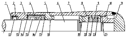
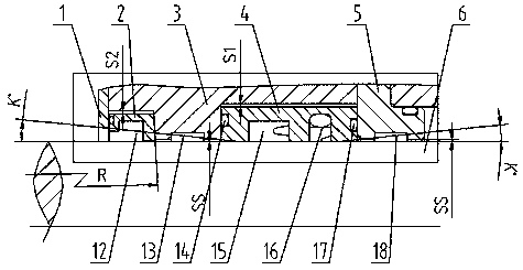
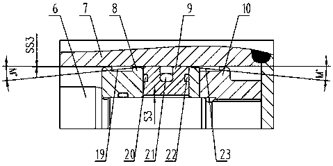
[0021] attached Figure 1-3 It is a specific embodiment of the present invention. The invention is an adaptive anti-side bending wear cylinder structure, including a cylinder 7, a piston rod end structure and a piston end structure, the cylinder 7 is provided with a piston rod 6, the cylinder 7 and the piston rod 6 The piston rod end structure and the piston end structure are respectively provided with separate support structures and sealing structures. The piston end structure is located at the end of the piston rod 6 in the cylinder barrel 7 close to the cylinder bottom 11, and the piston rod at the other end of the piston rod 6 The end structure is located at the cylinder 7, a guide sleeve is provided between the gland 1 and the cylinder 7, and the sealing structure is located between the guide sleeve and the piston rod 6.

[0022] Further, the supporting structure of the piston end structure includes a first split piston 8 and a second split piston 10, the sealing structu...


PUM


Abstract

The invention belongs to the technical field of oil cylinders and particularly relates to a self-adaption lateral-bending-wear-resisting oil cylinder structure comprising a cylinder barrel, a piston rod end structure and a piston end structure. A piston rod is arranged in the cylinder barrel. The piston rod end structure and the piston end structure between the cylinder barrel and the piston rod are provided with a separated type supporting structure and a seal structure correspondingly. The piston end structure is located at the end, close to the cylinder bottom, of the piston rod in the cylinder barrel. The piston rod end structure located at the other end of the piston rod is located at the cylinder barrel. A guide sleeve is arranged between a gland and the cylinder barrel. The seal structure is located between the guide sleeve and the piston rod. The self-adaption lateral-bending-wear-resisting oil cylinder structure has the beneficial effects that the independent seal structure is adopted and does not participate in support, a seal piece fluctuates along with the piston rod and the cylinder barrel, and the situation that the seal piece is stressed unilaterally can be effectively avoided; the independent support structure is adopted, so that a larger matching interval can be adopted, and the possibility that relative movement parts except a guide ring make contact due to flexure is effectively lowered.

Description

technical field [0001] The invention belongs to the technical field of oil cylinders, and in particular relates to a self-adaptive anti-side bending and wear-resistant oil cylinder structure. Background technique [0002] Some applications require cylinders with long installation distance, long stroke, high thrust, or side load requirements. Even if the pressure bar stability calculation check (Euler's formula) is satisfied, due to the limitation of traditional structure and machining accuracy, the cylinder is prone to side bending and component wear. [0003] Due to the long installation distance and stroke, the corresponding cylinder and piston rod are also long. During use, factors such as self-weight, thrust, and lateral force also cause the overall straightness of the cylinder to be inferior to short-stroke and short installation distance cylinders. . [0004] When the oil cylinder is placed horizontally, the self-weight will cause one side of the seal to be stressed,...

Claims


Application Information

Patent Timeline
Patent Type & Authority Applications(China)
IPC IPC(8): F15B15/14
CPCF15B15/1423F15B15/1452F15B15/1461
Inventor 郭晓春
Owner 无锡市汉为液压气动有限公司
Why Eureka
Try Eureka