A carbon dioxide blaster

A carbon dioxide and blaster technology, applied in blasting cylinders, weapon accessories, offensive equipment, etc., can solve the problems of separation, push rod damage, deformation, etc., and achieve the effect of increasing force and increasing friction

Active Publication Date: 2022-02-08
RANKEN RAILWAY CONSTR GROUP
View PDF5 Cites 0 Cited by
  • Summary
  • Abstract
  • Description
  • Claims
  • Application Information

AI Technical Summary

Problems solved by technology

Affected by the impact of blasting, the push rod at the end of the blasting tube is easy to separate from the rest of the blasting pipe or even pop out from the drill hole, resulting in damage and deformation of the push rod. , is not conducive to the recycling of blasting tubes

Method used


Image

  • A carbon dioxide blaster
  • A carbon dioxide blaster
  • A carbon dioxide blaster

Examples


Embodiment 1

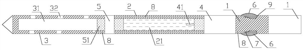
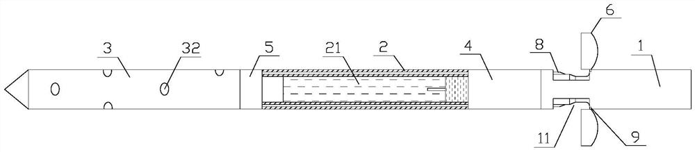
[0036] Such as Figure 1-5 As shown, a carbon dioxide blaster of the present invention includes a push rod 1, a liquid storage pipe 2 and an exhaust pipe 3, the liquid storage pipe 2 is provided with a liquid storage chamber 21, and the exhaust pipe 3 is provided with an exhaust chamber 31. The surface of the exhaust pipe 3 is provided with an exhaust hole 32, and the exhaust hole 32 communicates with the exhaust chamber 31. The push rod 1 and the liquid storage pipe 2 are connected through the first connector 4, and the liquid storage pipe 2 is connected to the exhaust chamber 31. The air pipes 3 are connected through the second connector 5, a heater 41 is arranged on the first connector, and a constant pressure shear piece 51 is arranged on the second connector 5, and the constant pressure shear piece 51 is arranged between the liquid storage chamber 21 and the exhaust gas. Between chambers 31.

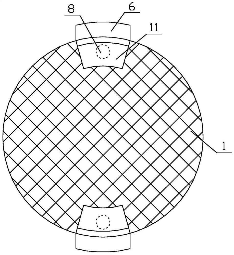
[0037] Further, the push rod 1 is provided with several grooves 11, the groove...

Embodiment 2

[0042] Such as Figure 1-5 As shown, a carbon dioxide blaster of the present invention includes a push rod 1, a liquid storage pipe 2 and an exhaust pipe 3, the liquid storage pipe 2 is provided with a liquid storage chamber 21, and the exhaust pipe 3 is provided with an exhaust chamber 31. The surface of the exhaust pipe 3 is provided with an exhaust hole 32, and the exhaust hole 32 communicates with the exhaust chamber 31. The push rod 1 and the liquid storage pipe 2 are connected through the first connector 4, and the liquid storage pipe 2 is connected to the exhaust chamber 31. The air pipes 3 are connected through the second connector 5, a heater 41 is arranged on the first connector, and a constant pressure shear piece 51 is arranged on the second connector 5, and the constant pressure shear piece 51 is arranged between the liquid storage chamber 21 and the exhaust gas. Between chambers 31.

[0043] Further, the push rod 1 is provided with several grooves 11, the groove...


PUM


Abstract

The invention discloses a carbon dioxide blaster, which comprises a push rod, a liquid storage pipe and an exhaust pipe. The liquid storage pipe is provided with a liquid storage chamber, the exhaust pipe is provided with an exhaust chamber, and the surface of the exhaust pipe is provided with an exhaust pipe. hole, the exhaust hole communicates with the exhaust cavity, the push rod and the liquid storage pipe are connected through the first connector, the liquid storage pipe and the exhaust pipe are connected through the second connector, and a heater is arranged on the first connector. A constant pressure shearing piece is arranged on the second connecting head, and the constant pressure shearing piece is arranged between the liquid storage chamber and the exhaust chamber. The carbon dioxide blaster can prevent the push rod from detaching and ejecting from the drill hole during blasting, avoiding damage and deformation of the push rod, and is beneficial to the recycling and reuse of the blasting pipe.

Description

technical field [0001] The invention relates to the field of engineering construction, in particular to a carbon dioxide blaster. Background technique [0002] Subgrade earthwork is one of the key processes of road construction projects. In construction, large hydraulic pick excavators such as 360 and 450 and down-the-hole drills are usually used in conjunction with large hydraulic wedges for construction. Due to the hard mining of some sections, it is difficult to mine. The efficiency is very low, and the construction schedule requirements cannot be met, and the construction cost also increases significantly. In order to ensure the smooth advancement of the construction progress, a new type of stone mining method has been developed: carbon dioxide (CO2) blasting technology. [0003] Liquid carbon dioxide phase change fracturing technology is a blasting technology with advanced concept, safe method and remarkable effect. It belongs to physical blasting technology. It has no...

Claims


Application Information

Patent Timeline
Patent Type & Authority Patents(China)
IPC IPC(8): F42B3/04F42B3/06E21C37/14
CPCF42B3/04F42B3/06E21C37/14
Inventor 于翔廖建东康文权胡运春白毅巫志农王威彭艳吕建钟伟刘会元
Owner RANKEN RAILWAY CONSTR GROUP
Why Eureka
Try Eureka