Handle structure for portable instrument, portable instrument and use method

A portable and handle technology, which is applied in the field of handle structure of portable instruments, can solve the problems of easy failure, single overall function, and inability to realize functions, etc., and achieve the effect of meeting the needs of use, simple overall structure, and enhanced versatility

Active Publication Date: 2021-06-04
CHINA ELECTRONIS TECH INSTR CO LTD
View PDF21 Cites 0 Cited by
  • Summary
  • Abstract
  • Description
  • Claims
  • Application Information

AI Technical Summary

Problems solved by technology

[0002] The handle is the handle of the instrument. The working conditions of the handle and the production process of the handle when the instrument is placed and transported are not fully considered in the design of the existing handle. The two handles have their own defects. The first handle is clamped on the rotating shaft on the shell. , without auxiliary limit device, theoretically there is a risk of overturning when the instrument is transported, and it cannot provide auxiliary support when the instrument is placed at an angle, and the overall function is relatively single, and rich functions cannot be realized; It is complex and unsatisfactory in reliability. The elastic force is provided by the compression and rebound of the spring. This structure is difficult to meet the requirements of portable instruments for the use of handles

Method used


Image

  • Handle structure for portable instrument, portable instrument and use method
  • Handle structure for portable instrument, portable instrument and use method
  • Handle structure for portable instrument, portable instrument and use method

Examples


Embodiment 1

[0043] As introduced in the background technology, there are deficiencies in the prior art. In order to solve the above technical problems, the present invention proposes a handle structure for portable instruments. The present invention will be further elaborated below in conjunction with the accompanying drawings.

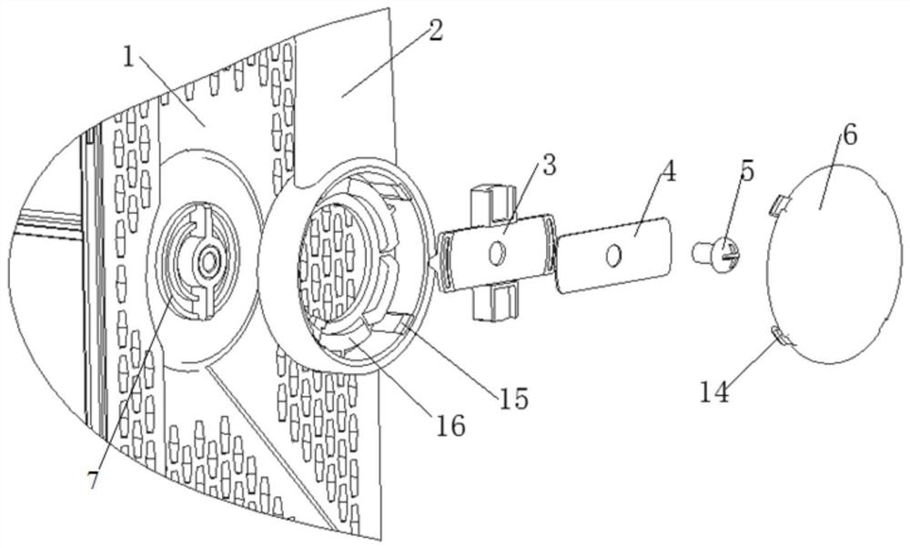
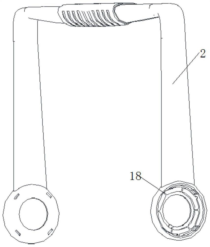
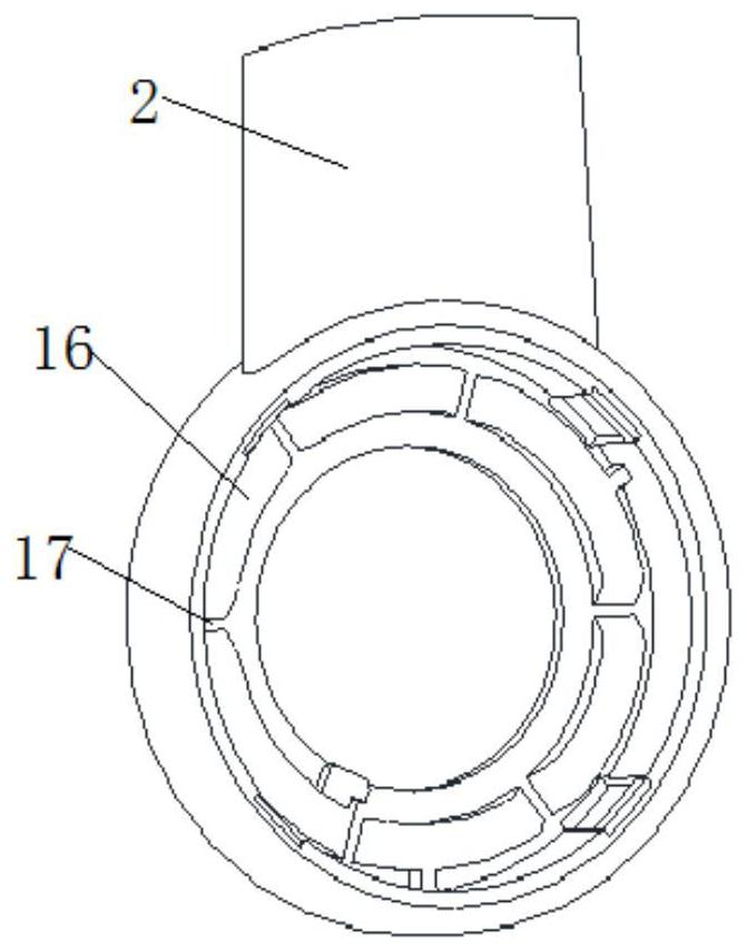
[0044] In a typical embodiment of the present invention, such as figure 1 As shown, a handle structure for a portable instrument includes a handle 2, a limit pressure block 3, a pressing piece 4 and a fastener 6, and the end of the handle 2 is a ring portion 18, such as figure 2 As shown, the ring part 18 is used to be clamped on the side of the housing 1, and the handle ring part 18 can be rotated relative to the housing under the action of an external force. The ring part 18 is provided with a groove, and multiple A locking slot 17, a plurality of fixed blocks 16 are arranged in the groove inner circle, the fixed block 16 is an arc block, and a locking slot 17...

Embodiment 2

[0052] A portable instrument, including a handle structure and a housing for a portable instrument described in Embodiment 1, the housing is not limited, one side or both sides of the housing are provided with a limiter 7, the limiter 7 includes a multi-ring Limiting ring 13, the middle part of limiting ring 13 is provided with threaded block 11, and threaded block 11 has threaded hole, is used for realizing fastening connection with the locking member of handle structure, and both sides of threaded block 11 are all provided with connecting rod 12 ,Such as Figure 5 As shown, the connecting rod 12 is connected with the limit ring 13, the connecting rod and the threaded block 11 are set higher than the limit ring 13, and the end connecting the connecting rod 11 and the outermost limit ring is provided with a slope, which is convenient for the handle to be round. The ring part 18 is installed on the limiting part 7, and the setting of the limiting part has two functions, one is ...


PUM


Abstract

The invention discloses a handle structure for a portable instrument, a portable instrument and a use method, which solve the problems of single handle structure and function, complicated setting and poor reliability in the prior art, and have the advantages of realizing the fixing of multiple gear handles. The beneficial effects of meeting the needs of portable use are as follows: a handle structure for a portable instrument, comprising a handle, one end of the handle is a circular ring part for engaging with a casing, the handle can be rotated relative to the casing, and the circular ring A groove is set in the inner part, a plurality of fixing blocks are arranged in the groove, and a clamping slot is formed between two adjacent fixing blocks; a limit pressure block, one side of the limit pressure block is provided with a limit that can cooperate with the clamping groove Protruding, and the limit pressure block can cooperate with the shell; the pressure piece, the pressure piece is arranged on the other side of the limit pressure block, the pressure piece is connected with the shell through the locking piece, and the locking piece passes through the limit Position pressure block and groove setting of the ring part.

Description

technical field [0001] The invention relates to the field of instruments, in particular to a handle structure for a portable instrument, a portable instrument and a use method. Background technique [0002] The handle is the handle of the instrument. The working conditions of the handle and the production process of the handle when the instrument is placed and transported are not fully considered in the design of the existing handle. The two handles have their own defects. The first handle is clamped on the rotating shaft on the shell. , without auxiliary limit device, theoretically there is a risk of overturning when the instrument is transported, and it cannot provide auxiliary support when the instrument is placed at an angle, and the overall function is relatively single, and rich functions cannot be realized; It is complex and unsatisfactory in reliability. The elastic force is provided by the compression and rebound of the spring. This structure is difficult to meet t...

Claims


Application Information

Patent Timeline
Patent Type & Authority Patents(China)
IPC IPC(8): G01D11/20G01D11/16B25G3/02B25G3/12
CPCB25G3/02B25G3/12G01D11/16G01D11/20
Inventor 安帅伟史亚婷孙桂清
Owner CHINA ELECTRONIS TECH INSTR CO LTD
Why Eureka
Try Eureka