Hybrid touch module
A touch module and hybrid technology, applied in instruments, computing, electrical and digital data processing, etc., can solve the problems of thick product thickness, high material cost, and high restrictions, and achieve reduced thickness and material cost, wide operating conditions, The effect of preventing accidental touch
- Summary
- Abstract
- Description
- Claims
- Application Information
AI Technical Summary
Problems solved by technology
Method used
Image

Examples
no. 1 example
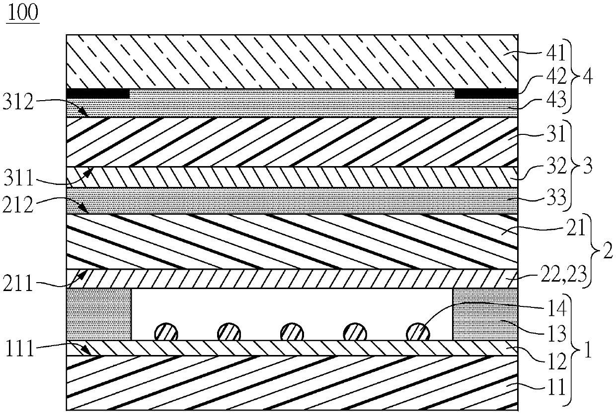
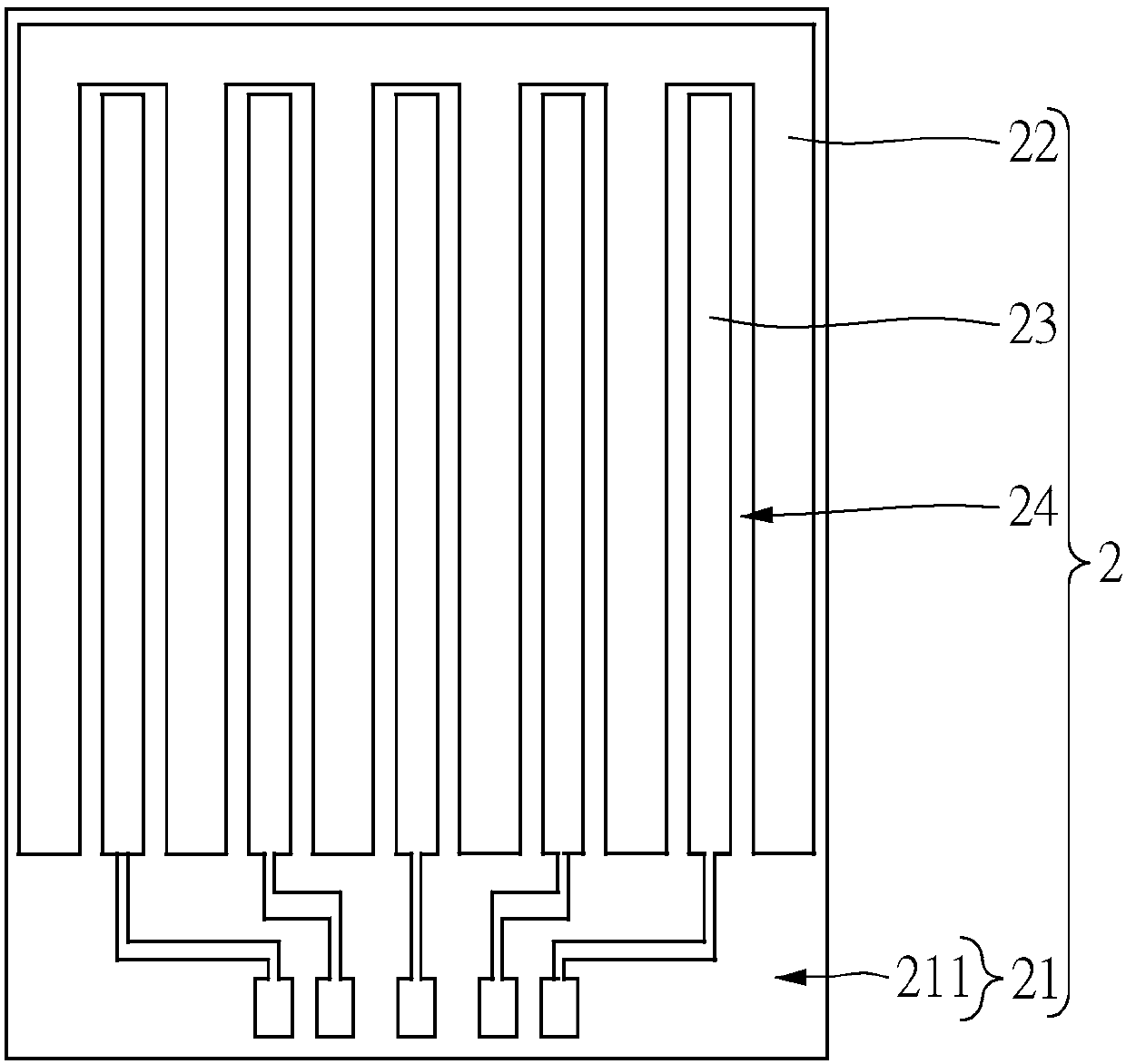
[0027] Such as figure 1 , figure 2 and Figure 4 , which is the first embodiment of the present invention. This embodiment discloses a hybrid touch module 100, which can be used to provide a resistive touch function and a capacitive touch function, and the hybrid touch module 100 can be applied to smart phones, tablet computers, Laptops, or industrial computers and other electronic products. The hybrid touch module 100 includes a bottom structure 1, a shared layer structure 2 disposed on the bottom structure 1, a top layer structure 3 attached to the shared layer structure 2, and a top layer structure attached to the shared layer structure 2. A protective structure 4 on the top structure 3. Furthermore, the hybrid touch module 100 further includes a shared controller 5 (such as Figure 4 ). The specific structure of each component of the hybrid touch module 100 in this embodiment will be described below, and then the connection relationship between each component of the...
no. 2 example
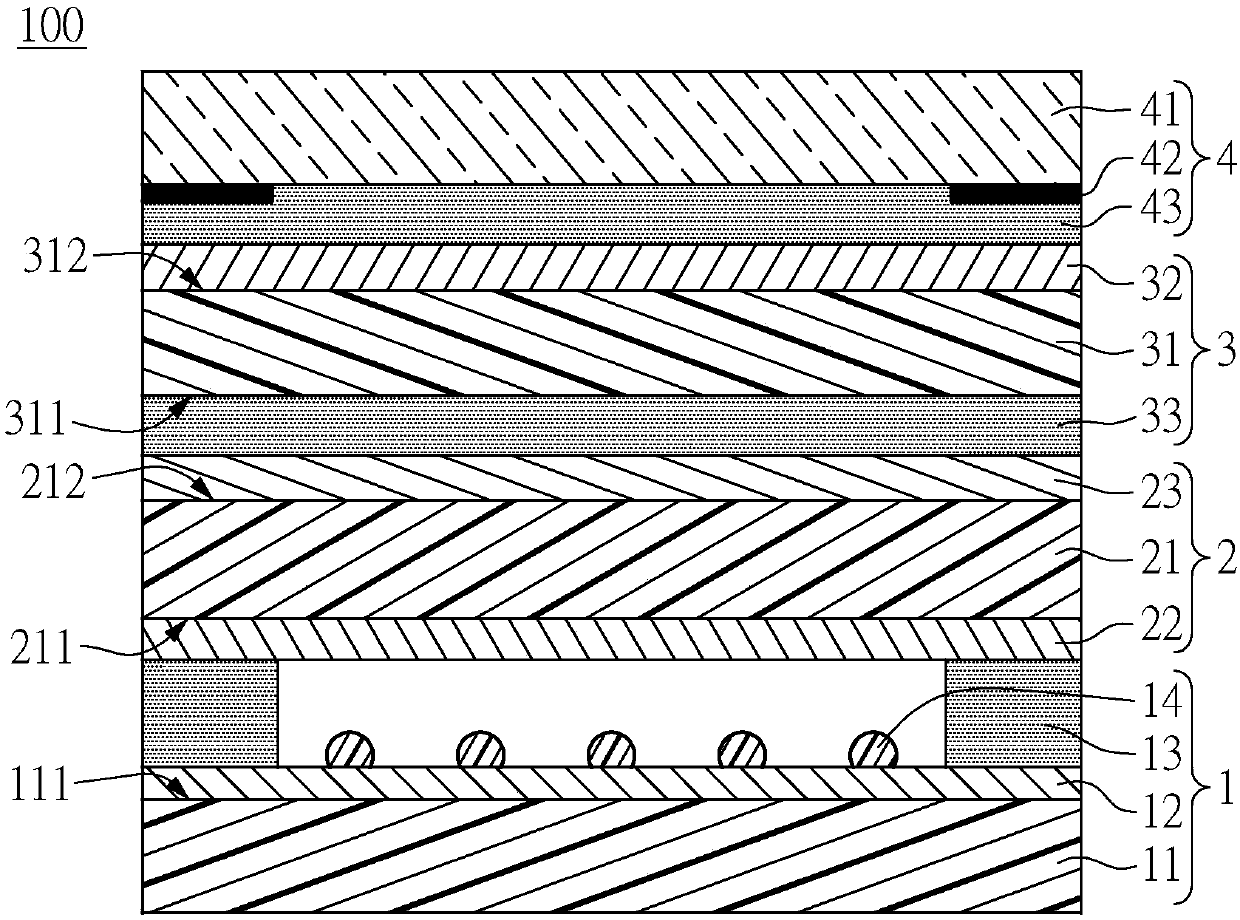
[0046] Such as image 3 , which is the second embodiment of the present invention. This embodiment discloses a hybrid touch module 100 , which includes a bottom layer structure 1 , a shared layer structure 2 , a top layer structure 3 , a protection structure 4 , and a shared controller 5 . The structural design and location arrangement relationship of the underlying structure 1 , the protection structure 4 , and the common controller 5 in this embodiment are substantially the same as those in the first embodiment. The difference lies in the structural design and position arrangement of the common layer structure 2 and the top layer structure 3 . The difference between this embodiment and the first embodiment will be described below.
[0047] The capacitor conductive layer 23 of the common layer structure 2 of this embodiment is disposed on the second surface 212 of the common film 21 , and the electrode layer 32 of the top layer structure 3 is disposed on the top surface 312...
no. 3 example
[0051] Such as Figure 5 and Figure 6 , which is the third embodiment of the present invention. This embodiment discloses a hybrid touch module 100 , which includes a bottom layer structure 1 , a shared layer structure 2 , a protection structure 4 , and a shared controller 5 . The structural design of each component of this embodiment is substantially the same as that of the second embodiment. The biggest difference between this embodiment and the second embodiment is that the hybrid touch module 100 of this embodiment does not have the top structure 3 . The difference between this embodiment and the first embodiment will be described below.
[0052] Since the hybrid touch module 100 of this embodiment does not have a top layer structure 3, the hybrid touch module 100 of this embodiment provides a capacitive touch sensor by sharing the capacitive conductive layer 23 and the common film 21 of the layer structure 2. control function. That is to say, the common layer struct...
PUM
 Abstract
Description
Claims
Application Information
 - Generate Ideas
- Intellectual Property
- Life Sciences
- Materials
- Tech Scout
- Unparalleled Data Quality
- Higher Quality Content
- 60% Fewer Hallucinations
Browse by: Latest US Patents, China's latest patents, Technical Efficacy Thesaurus, Application Domain, Technology Topic, Popular Technical Reports.
© 2025 PatSnap. All rights reserved.Legal|Privacy policy|Modern Slavery Act Transparency Statement|Sitemap|About US| Contact US: help@patsnap.com