Anti-interlocking device and its distribution cabinet

A technology of interlocking device and mounting frame, which is applied in the substation/power distribution device shell, air switch parts, etc., and can solve the problems of inoperability, rotation and operation of the grounding switch

Active Publication Date: 2021-04-27
ANHUI QUEUE ELECTRIC
View PDF1 Cites 0 Cited by
  • Summary
  • Abstract
  • Description
  • Claims
  • Application Information

AI Technical Summary

Problems solved by technology

[0003] The publication number is CN106158455B, which provides a high-voltage switch cabinet anti-interlock device applied in the technical field of high-voltage switch cabinet components. When the rear door panel is not closed, the curved plate and the stop rod of the anti-interlock device body are under the elastic force of the spring. It protrudes toward the defense line close to the rear door panel, and the part of the bent plate and the retaining rod protrudes from the side plate more, so that when the rear door panel is not closed, the retaining rod can effectively prevent the rotation of the interlocking piece, and the linkage piece cannot rotate, that is, it is grounded The large shaft of the switch cannot be rotated, so that the grounding switch cannot be operated to avoid misoperation, and this device cannot be used in some cases where the cabinet door needs to be opened and the circuit is still connected

Method used


Image

  • Anti-interlocking device and its distribution cabinet
  • Anti-interlocking device and its distribution cabinet
  • Anti-interlocking device and its distribution cabinet

Examples


Embodiment

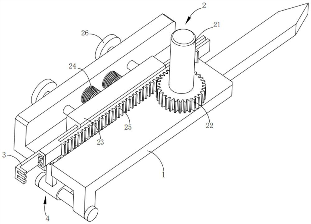
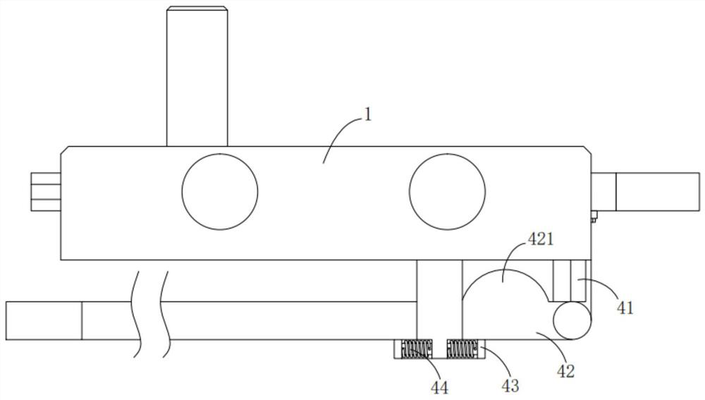
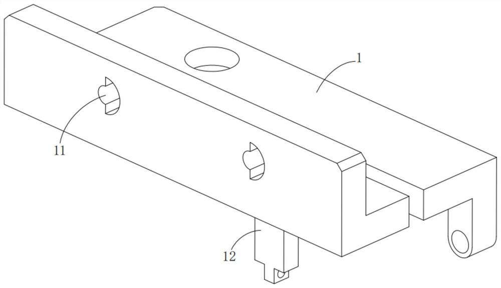
[0025] see Figure 1 to Figure 4 , the present invention provides a technical solution:

[0026] An anti-interlocking device, including a support frame 1, a driving mechanism 2, a switch knife connecting frame 3 and a grounding mechanism 4, wherein:

[0027] The supporting frame 1 is provided with a semicircular mounting hole 11 and a mounting frame 12 is provided at the bottom thereof, the driving mechanism 2 includes a rotating shaft 21, a gear 22, a linear guide rail 23, a spring 24, a rack 25 and a support rod 26, and the rotating shaft 21 passes through the bearing Installed on the support frame 1, the end of which is sleeved with a gear 22, and the two ends of the linear guide rail 23 are rotatably installed with a support rod 26, wherein the support rod 26 runs through the support frame 1 and forms a moving pair with the support frame 1, wherein The support rod 26 is provided with a semicircular catch 261, and the semicircular catch 261 on the support rod 26 fits in th...


PUM


Abstract

The invention provides an anti-interlock device and its power distribution cabinet, wherein the anti-interlock device includes a support frame, a driving mechanism, a switch knife connecting frame and a grounding mechanism, the rotating shaft in the driving mechanism is installed on the support frame, and its end There are gears in the fixed sleeve, and support rods are installed on both ends of the linear guide rail. The support rods pass through the support frame and form a moving pair with the support frame. There is a spring between the linear guide rail and the support frame. On the guide rail, the rack is meshed with the gear, the knife connecting frame is installed at the end of the rack, and the grounding mechanism is arranged at the bottom of the support frame and connected with the rack in transmission. The racks in the driving mechanism respectively drive the blade connection frame and the grounding mechanism to realize the disconnection and grounding of the blades, and the semicircular baffle on the support rod is separated from the semicircular mounting hole, and then the linear guide rail retreats. At this time, the gear The bar is disengaged from the gear, and then the connection between the power input components is disconnected, which avoids the occurrence of misoperation.

Description

technical field [0001] The invention relates to the technical field of power distribution cabinet components, in particular to an anti-interlock device and a power distribution cabinet. Background technique [0002] The interlocking mechanism of the power distribution cabinet door is a device installed on high-voltage power distribution switch cabinets and other equipment to interlock with the grounding switch and the opening / closing of the power distribution cabinet door. Dangerous, in the absence of power failure and grounding, operators and maintenance personnel cannot open the cabinet door of the power distribution cabinet for maintenance and inspection work. The door interlocking mechanism of the power distribution cabinet is a mechanism that interlocks with the accessories on the door of the power distribution cabinet through the opening and closing operation of the grounding switch in the power distribution cabinet to ensure the safety of operators and maintenance per...

Claims


Application Information

Patent Timeline
Patent Type & Authority Patents(China)
IPC IPC(8): H01H31/06H02B1/30
CPCH01H31/06H02B1/30
Inventor 石敏王建郭玉文单钜程葛学章刘凯楚卫民侯骏张惠忠侯金华张雅雯黄健
Owner ANHUI QUEUE ELECTRIC
Why Eureka
Try Eureka