
Loop for monitoring conductive pollution

A conductivity and circuit technology, which is applied in the field of monitoring conductive pollution circuits, can solve the problems of low monitoring accuracy, false alarms of optical signal instruments, high maintenance costs, etc., and achieve the effect of avoiding potential safety hazards

Pending Publication Date: 2019-09-20
RENERGY ELECTRIC TIANJIN
View PDF0 Cites 0 Cited by
  • Summary
  • Abstract
  • Description
  • Claims
  • Application Information

AI Technical Summary

Problems solved by technology

And because of the air flow, at some point, the attenuation of the optical signal may cause the instrument to falsely report
Therefore, when using optical signal monitoring instruments, for some industrial-grade electrical equipment, the monitoring accuracy is extremely low, and the light source needs to be cleaned regularly, resulting in higher maintenance costs in the later period

Method used


Image

  • Loop for monitoring conductive pollution

Examples


Embodiment Construction

[0017] It should be noted that, in the case of no conflict, the embodiments of the present invention and the features in the embodiments can be combined with each other.

[0018] The present invention will be described in detail below with reference to the accompanying drawings and examples.

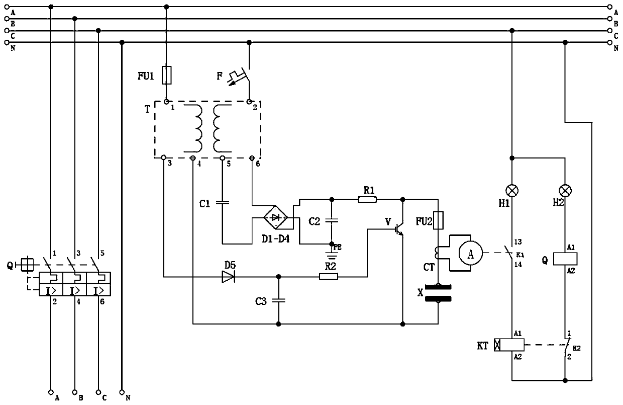
[0019] Such as figure 1 As shown, a circuit for monitoring conductive pollution includes a main circuit power supply and a main circuit breaker Q, the input end of the main circuit breaker Q is connected to the main circuit power supply, and the output end is connected to an electrical load. The loop power supply is connected to an uncontrolled rectification circuit, the output end of the uncontrolled rectification circuit is connected to both ends of the discharge gap X, and one end of the discharge gap X is connected to a current sensor CT, and the current sensor CT is connected to the monitoring circuit , the monitoring circuit is used to monitor whether there is conductive pollution...


PUM


Abstract

The invention provides a loop for monitoring conductive pollution. The loop comprises a main loop power supply and a main loop circuit breaker Q, wherein the input end of the main loop circuit breaker Q is connected with the main loop power supply, while the output end is connected with an electric load; the main loop power supply is connected with an uncontrolled rectifying circuit, and the output end of the uncontrolled rectifying circuit is connected to the two ends of a discharging gap X; and one end of the discharging gap X is connected with a current sensor CT, and the current sensor CT is connected with a monitoring circuit. The loop has the beneficial effects that the problem that most conductive pollution cannot be effectively monitored in a closed charged space is solved, and an early warning signal can be sent out when the concentration of a conductive pollution source is too large. All or part of the power supply is cut off through an external control protection device, so that potential safety hazards caused by too much conductive pollution in the closed space are avoided.

Description

technical field [0001] The invention belongs to the field of electric power application, in particular to a circuit for monitoring conductive pollution. Background technique [0002] Inside the existing cabinets, electrical components are often short-circuited due to untimely maintenance, insufficient IP rating, sudden dust pollution and other reasons, which may cause fire and other dangers in severe cases. [0003] At present, most monitoring instruments on the market use the attenuation principle of optical signals. When the dust concentration is too large, the light source signal received by the receiving end attenuates to a certain threshold, and is converted into a digital or analog signal through the back-end circuit. [0004] But in most electrical equipment used outdoors, a small amount of dust suspended in the air will not cause malfunction. And because of the air flow, at some point, the attenuation of the optical signal may cause false alarms of the instrument. ...

Claims


Application Information

Patent Timeline
Patent Type & Authority Applications(China)
IPC IPC(8): H02H7/22
CPCH02H7/22
Inventor 费强于爽
Owner RENERGY ELECTRIC TIANJIN
Learn More