Multi-beam Optical Thick Film Monitor

A monitor and multi-beam technology, applied in the direction of using optical devices, instruments, measuring devices, etc., can solve the problems of low monitoring accuracy, poor monitoring efficiency, and few monitoring points, so as to achieve more monitoring points, improve yield rate, and low cost Effect

Active Publication Date: 2017-11-14
杰莱特(苏州)精密仪器有限公司
View PDF7 Cites 0 Cited by
  • Summary
  • Abstract
  • Description
  • Claims
  • Application Information

AI Technical Summary

Problems solved by technology

[0004] The purpose of the present invention is to solve the technical problems of few monitoring points, low monitoring precision and poor monitoring efficiency existing in the existing optical film thickness meter, and to provide a multi-beam optical thick film monitor

Method used


Image

  • Multi-beam Optical Thick Film Monitor
  • Multi-beam Optical Thick Film Monitor

Examples


Embodiment Construction

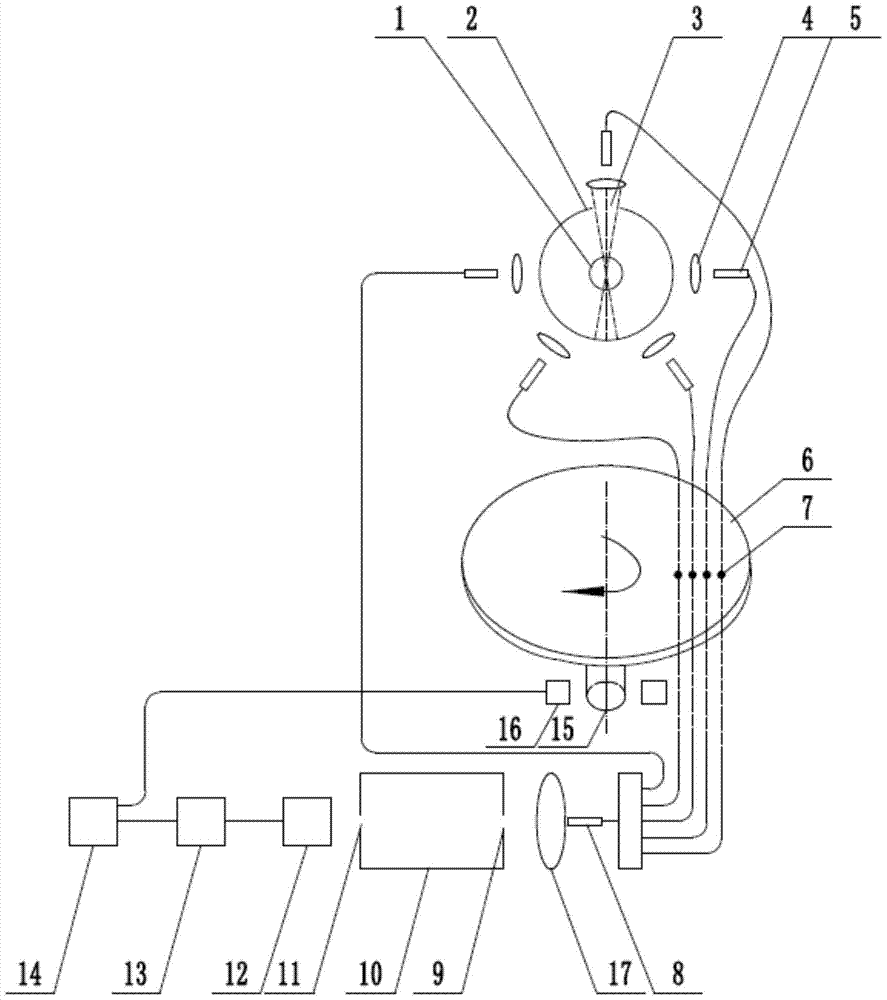
[0017] like figure 1 As shown, the multi-beam optical thick film monitor in this embodiment includes a monochromator 10, a photodetector 12, a signal amplifier 13, a control computer 14, a position trigger circuit 16 and a converging lens 17, wherein: it also includes :

[0018] A tungsten-halogen lamp 1: the tungsten-halogen lamp 1 is set in the annular rotary chopper 2;

[0019] A ring-shaped rotary light chopper 2: the circular ring-shaped rotary light chopper 2 is set on a rotating tray and can rotate around the filament of the tungsten-halogen lamp 1; A light exit hole 3, a photoelectric switch or an encoder is coaxially connected to the axis of the annular rotary chopper 2 to set trigger pulses for each optical path and dark field position for selecting the corresponding signal processing circuit;

[0020] Five optical fiber optical paths: each optical fiber optical path is composed of a lens 4 and an optical fiber 5. The optical fiber optical path is centered on the f...


PUM


Abstract

The invention involves a multi -optical beam optical thick film monitor, which belongs to a real -time monitoring equipment of optical coating.The present invention mainly solves technical problems with the existing optical membrane thick monitoring points, low monitoring accuracy, and poor monitoring efficiency.The technical solution adopted by the present invention is: multi -optical beam optical thick film monitor, which includes monochrome, photoelectric detectors, signal amplifiers, control computers, position touch circuits, and clustering lenses.A rotary cutter: The rotary cutting device is set on a rotating tray and can be rotated with halogen tungsten lamp filament; at least three optical fiber light paths: each optical fiber light routing is composed of lens and fiber; substrate brackets: substrate brackets are located onBelow the rotation of the light cutter, the monitoring point is located on the substrate bracket.The present invention has the advantages of multiple monitoring points, high monitoring accuracy and low cost.

Description

technical field [0001] The invention relates to a multi-beam optical thick film monitor, which belongs to an optical coating real-time monitoring device. Background technique [0002] During the vacuum coating process, the monitoring of the film thickness is accomplished by an optical film thickness monitor. The monitoring of film thickness is: the light beam generated by the light source is chopped and modulated by the optical chopper and then passes through the glass to be measured or is reflected. With the continuous deposition of materials during the coating process, the thickness of the film layer changes continuously, and the transmission of the film layer The efficiency also changes accordingly due to the interference effect of light. The optical signal is introduced into the monochromator by using an optical fiber, and the light of the required monitoring wavelength is filtered out by the exit slit. The monochromatic light signal is converted into an electrical signa...

Claims


Application Information

Patent Timeline
Patent Type & Authority Patents(China)
IPC IPC(8): G01B11/06
Inventor 张殷邓琪张小飞王静辉吕子啸
Owner 杰莱特(苏州)精密仪器有限公司
Why Eureka
Try Eureka