Guide blade type high-pressure cyclone separator

A cyclone separator and vane-type technology, which is applied in the field of vane-type high-pressure cyclone separators, can solve the problems of less particle back-mixing, suspended stagnant airflow, poor effect, and no extension of insertion depth, etc., to achieve significant separation effect, constant pressure drop, ideal separation performance

Pending Publication Date: 2019-09-24
XIHUA UNIV
View PDF0 Cites 1 Cited by
  • Summary
  • Abstract
  • Description
  • Claims
  • Application Information

AI Technical Summary

Problems solved by technology

After reviewing and researching related materials such as the geometric structure of the blade, parameter values, and the structural size of the exhaust pipe, it is found that there are very few arguments for the phenomenon of short-circuit flow, particle back-mixing, and suspended stagnant airflow. , the effect of improving the above problems may not be good, so we mainly explore the improvement measures of the exhaust pipe
At present, most of the research on the exhaust pipe focuses on its body structure. For example, when the insertion depth is short, only the inlet end is changed to a narrow or wide mouth; or, the part inserted into the cylinder is slotted to improve separation. performance; but there is no practice of extending the insertion depth and adding components. Based on this, this paper proposes a vane-type high-pressure cyclone separator with the function of diversion and filtration

Method used


Image

  • Guide blade type high-pressure cyclone separator
  • Guide blade type high-pressure cyclone separator
  • Guide blade type high-pressure cyclone separator

Examples


Embodiment Construction

[0040] The present invention is further described below in conjunction with specific embodiment, and specific embodiment is the further description of the principle of the present invention, does not limit the present invention in any way, and the identical or similar technology of the present invention all does not exceed the scope of protection of the present invention.

[0041] In conjunction with the accompanying drawings.

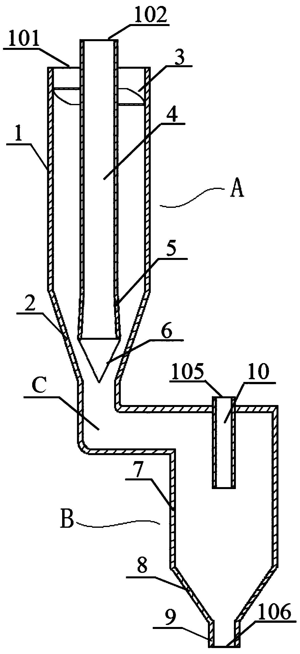
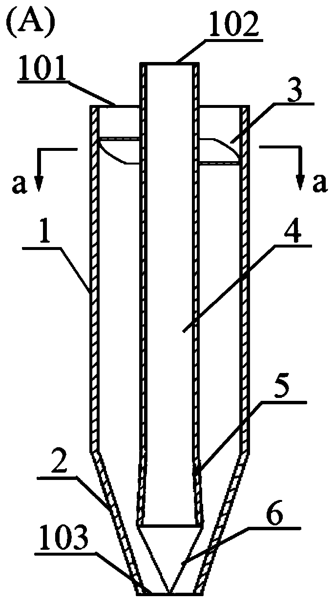
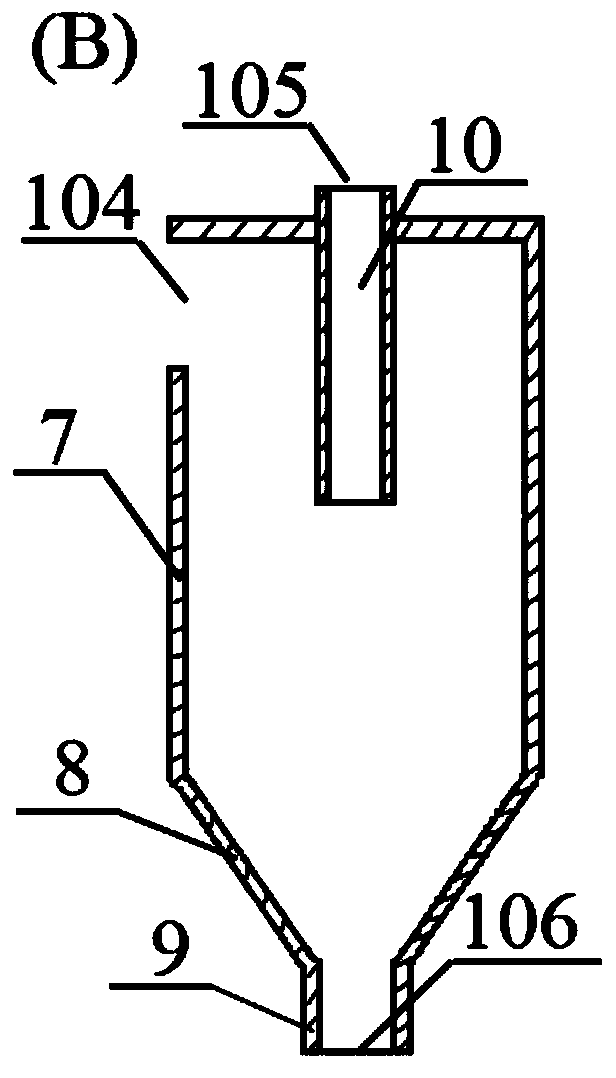
[0042] In this example, the vane-type high-pressure cyclone separator with the function of diversion and filtration includes separation unit A, secondary separation unit B and connecting elbow C; separation unit A includes an upper cylindrical cylinder 1, a lower cone 2, a diversion unit Blade 3, exhaust pipe 4, filter member 5 and guide cone 6; secondary separation unit B includes cylindrical shell 7, conical hopper 8, dust discharge pipe 9 and secondary exhaust pipe 10; the connecting bend in this example The angle of tube C is 90°~120°.

[0043]The...


PUM


Abstract

The invention discloses a guide blade type high-pressure cyclone separator with a flow guiding filtration function. A separation unit shell body is composed of an upper column-shaped cylinder body and a lower cone body, flow guide blades serving as cyclone parts are of arc surface structures with a certain thickness and are fixed between an air exhausting pipe and the column-shaped cylinder body, and every two adjacent blades form a spiral flow passage; gaps are reserved between the tops of the blades and the top of the column-shaped cylinder body, the air exhausting pipe penetrates through the top axis of the column-shaped cylinder body and extends downward to the bottom of the cylinder body, a trumpet-shaped filtration component with a special hole form is additionally arranged, a narrow port of the trumpet-shaped filtration component is welded with the tail end of the air exhausting pipe, and the wide port end of the trumpet-shaped filtration component is fixedly connected with a flow guiding cone. A separation unit is communicated with a second-level separation unit through a bent connection pipe, and the second-level separation unit is composed of a second-level air exhausting pipe, a dust discharging pipe and the shell body. Through sleeving arrangement of the filtration component and the flow guiding cone, backmixing particles carried by inward rotation flow are removed, the tail swinging phenomenon occurring on the tail end of the inward rotation flow is inhibited, remaining airflow with dust is guided in entering the second-level separation unit, the airflow stopping phenomenon caused by a vortex at an inlet of the cone body is avoided, and the separation purity is improved.

Description

technical field [0001] The invention belongs to the technical field of mechanical design and manufacture, in particular to the technical field of cyclone separator design, and is mainly used as a gas-solid two-phase separation device, in particular to a vane-type high-pressure cyclone separator with the function of diversion and filtration. Background technique [0002] As an important gas-solid separation equipment, the cyclone separator has been widely used in many industries such as petrochemical industry, coal-fired power generation and environmental protection. Compared with other gas-solid separation technologies, it has the advantages of simple structure, no moving parts, low maintenance And the characteristics of low operating cost. The traditional cyclone separator usually has a rectangular or volute-type tangential inlet, and its inherent air intake method makes the pressure loss relatively large, which is not conducive to the working environment of high pressure a...

Claims


Application Information

Patent Timeline
Patent Type & Authority Applications(China)
IPC IPC(8): B01D50/00
CPCB01D50/20
Inventor 赖喜德宁楠叶道星陈小明康定忠
Owner XIHUA UNIV
Why Eureka
Try Eureka