Coupled Resonant Filter and Its Debugging Method

A technology of coupling resonance and debugging method, applied in waveguide-type devices, circuits, electrical components, etc., can solve the problems of small power capacity, poor insertion loss, increase the size and weight of the filter, etc., to achieve low voltage standing wave ratio, high Out-of-band rejection and low insertion loss

Active Publication Date: 2021-12-03
FUJIAN XINGHAI COMM TECH
View PDF5 Cites 0 Cited by
  • Summary
  • Abstract
  • Description
  • Claims
  • Application Information

AI Technical Summary

Problems solved by technology

[0003] However, traditional solutions are often only solutions for individual performance requirements. For example, in the prior art, the improvement of out-of-band rejection is achieved by increasing the number of resonant cavities. On the one hand, increasing the number of resonant cavities will increase The volume and weight of the filter; on the other hand, the increase of the resonant cavity leads to an increase in the number of tuning rods, which makes simulation and debugging more difficult and prolongs the design and debugging cycle
Another way to improve the out-of-band rejection is to use an intra-cavity cross-coupling structure, that is, to connect two non-adjacent resonant cavities with conductors inside the filter for proper coupling, which brings problems and makes debugging difficult, and the steps are cumbersome. The performance curve cannot be presented on the network analyzer in real time; at the same time, the cavities that use the cross-coupling need to be folded, so that the cavities that are not adjacent in space become adjacent in space, which increases the processing difficulty; in the prior art , the traditional method of reducing the size of the filter is to use the LC lumped filter structure, which brings at least three problems: small power capacity, poor insertion loss, and difficulty in mass production
[0004] That is to say, the existing filter has the problem of not being able to achieve the balance of multiple indicators

Method used


Image

  • Coupled Resonant Filter and Its Debugging Method
  • Coupled Resonant Filter and Its Debugging Method
  • Coupled Resonant Filter and Its Debugging Method

Examples


Embodiment 1

[0064] Please refer to Figure 1 to Figure 6 , Embodiment 1 of the present invention is:

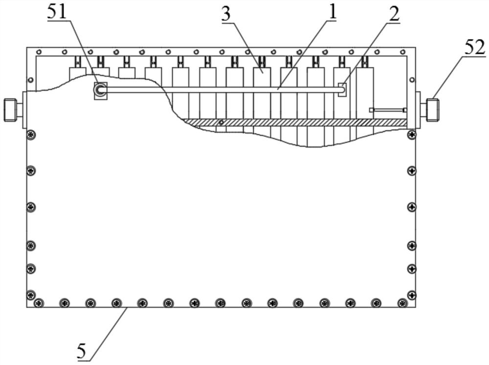
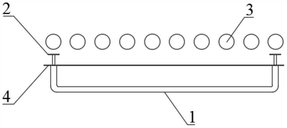
[0065] The coupled resonant filter includes a resonant rod 3, a filter outer conductor 4, a coaxial transmission line 1, a metal diaphragm 2, and a cover plate 5. The resonant rod 3 is located in the filter outer conductor 4, and the cover plate is fixed by the assembly screws 52 at both ends. 5 is fixed outside the outer conductor 4 of the filter, the two ends of the coaxial transmission line 1 pass through the outer conductor 4 of the filter respectively and the two ends of the coaxial transmission line 1 are respectively connected to the outer conductor 4 of the filter; the two ends of the coaxial transmission line 1 The ends are respectively connected with a metal diaphragm 2, and the metal diaphragm 2 faces the resonant rod 3.

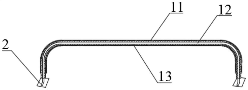
[0066] Wherein, the coaxial transmission line 1 includes a coaxial outer conductor 11 , a coaxial medium 13 , and a coaxial inner conductor 12 from outside...

Embodiment 2

[0072] Please refer to Figure 1 to Figure 6 , the second embodiment of the present invention is:

[0073] For the coupled resonant filter, on the basis of the first embodiment above, the coaxial medium 13 and the coaxial inner conductor 12 both pass through the filter outer conductor 4 .

Embodiment 3

[0074] Please refer to Figure 7 , Embodiment three of the present invention is:

[0075] The debugging method of the coupled resonant filter, the two ends of the coaxial transmission line are the first end and the second end, the metal diaphragm connected to the first end is the first metal diaphragm, and the metal diaphragm connected to the second end is the second metal diaphragm. Diaphragm. After the filter is connected to a vector network analyzer, the method for debugging the coupled resonant filter in the first embodiment includes steps:

[0076] Adjust the distance between the first metal diaphragm and the resonant rod by pulling the coaxial transmission line, weld the first end and the cover plate, and assemble the cover plate on the outer conductor of the filter;

[0077] Adjust the distance between the second metal diaphragm and the resonant rod by pulling the coaxial transmission line, and judge whether the out-of-band suppression of the coupled resonant filter m...


PUM


Abstract

The invention discloses a coupled resonant filter and a debugging method thereof, comprising a resonant rod, a coaxial transmission line, a metal diaphragm and an outer conductor of the filter, the resonant rod is located in the outer conductor of the filter, and the two ends of the coaxial transmission line respectively pass through the filter The outer conductor and the two ends of the coaxial transmission line are respectively movably connected to the outer conductor of the filter; the two ends of the coaxial transmission line are respectively connected with a metal diaphragm, and the metal diaphragm is facing the resonant rod; In some cases, the distance between the cross-coupled metal diaphragm and the resonant rod is adjusted by pulling the coaxial transmission line, thereby adjusting the coupling size, which is a good solution to the problem that the cross-coupling structure filter in the traditional cavity can only be adjusted by opening the filter shell. The problem of difficult debugging brought about by the cross-coupling structure can achieve the technical effect of balancing multiple indicators at the same time.

Description

technical field [0001] The invention relates to the field of filters in the field of microwave passive circuits, in particular to a coupling resonant filter and a debugging method thereof. Background technique [0002] The function of the filter is to pass the signal of a specific frequency and attenuate the signal outside the frequency. The performance requirements of some filters are: small size, high out-of-band rejection, low insertion loss, low voltage standing wave ratio, high power and other multi-index balance and optimal realization. The traditional method is to realize by increasing the number of resonant cavities, adopting LC lumped filter structure or cross-coupling structure. [0003] However, traditional solutions are often only solutions for individual performance requirements. For example, in the prior art, the improvement of out-of-band rejection is achieved by increasing the number of resonant cavities. On the one hand, increasing the number of resonant ca...

Claims


Application Information

Patent Timeline
Patent Type & Authority Patents(China)
IPC IPC(8): H01P1/203
CPCH01P1/203
Inventor 王中锋汪飘孔方方吴保义刘自富
Owner FUJIAN XINGHAI COMM TECH
Why Eureka
Try Eureka