Combined type pulp shaft

A combined paddle shaft technology, which is applied in the direction of conveying filamentous materials, thin material processing, transportation and packaging, etc., can solve the problems of unfavorable paddle shaft replacement and transportation, increase the workload of operators, unfavorable paddle shaft maintenance and treatment, etc. , to achieve the effect of fast and flexible disassembly and assembly operation, improve the effect of winding, and ensure the tightness of winding

Pending Publication Date: 2019-09-27
JIHUA 3542 TEXTILE CO LTD
View PDF0 Cites 0 Cited by
  • Summary
  • Abstract
  • Description
  • Claims
  • Application Information

AI Technical Summary

Problems solved by technology

[0003] However, the existing propeller shafts usually adopt an integrated structural design, resulting in a very strong integrity of the propeller shaft. When the parts on the propeller shaft are damaged and need to be replaced, the mainten

Method used


Image

  • Combined type pulp shaft
  • Combined type pulp shaft
  • Combined type pulp shaft

Examples


Embodiment Construction

[0058] The following will clearly and completely describe the technical solutions in the embodiments of the present invention with reference to the accompanying drawings in the embodiments of the present invention. Obviously, the described embodiments are only some, not all, embodiments of the present invention.

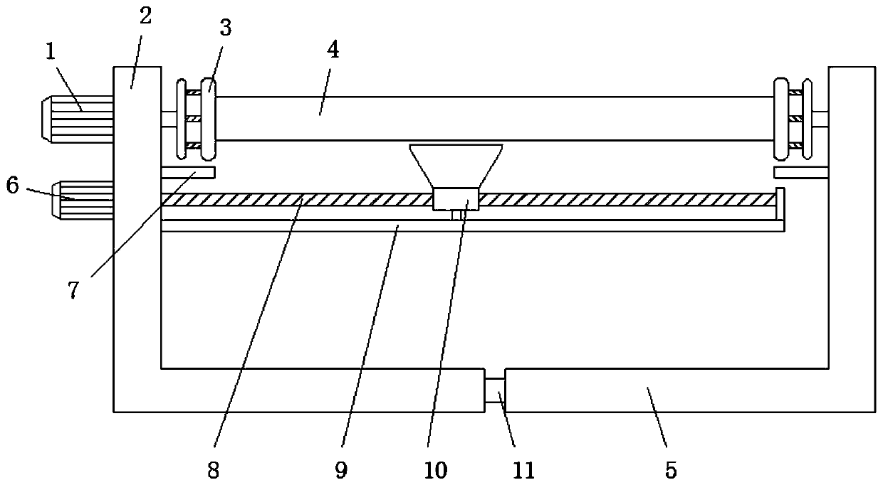
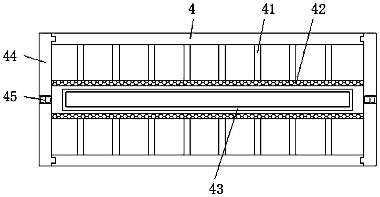
[0059] Such as figure 1 with figure 2 As shown, a combined paddle shaft includes a first mounting frame 2, a paddle shaft 4 and a second mounting frame 5;

[0060] Both the first mounting frame 2 and the second mounting frame 5 are L-shaped structures, and the opening directions of the angles at the bends of the first mounting frame 2 and the second mounting frame 5 are opposite;

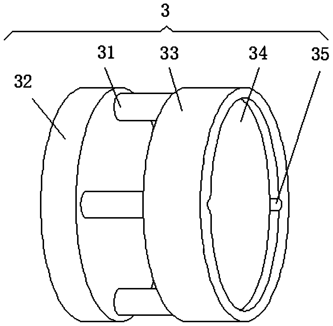
[0061] The outer wall bolts at the vertical end of the first installation frame 2 are fixed with a coiling motor 1, and the coiling motor 1 is connected to the connecting assembly 3 through a coupling. The coiling motor 1 can be a conventional servo motor on the market, which can effecti...


PUM


Abstract

The invention discloses a combined type pulp shaft. The combined type pulp shaft comprises a first installing frame, a pulp shaft body and a second installing frame. Both the first installing frame and the second installing frame are of an L-shaped structure. An electronic-controlled push rod is arranged inside a horizontal end of the first installing frame in an embedded manner, and the electronic-controlled push rod is connected with a horizontal end of the second installing frame through a transmission rod. A coiling motor is fixed on the outer wall of a vertical end of the first installing frame through bolts, and the coiling motor is in transmission connection with connecting assemblies through shaft coupling. The number of theconnecting assemblies is two. The pulp shaft body is clamped, connected and fixed between the two connecting assemblies. According to the combined type pulp shaft, a split-combined type structural design is adopted by the pulp shaft body; the rapid and flexible disassembling and assembling operation effect of the pulp shaft body is achieved; the pulp shaft body is conveniently and rapidly installed on the coiling mechanism so that coiling treatment of the pulp shaft body can be conducted; and when components and parts of the pulp shaft body break down and are damaged, repair and replacement treatment can also be conducted on the damaged components and parts atthe first time; and workload of operating staff is lowered.

Description

technical field [0001] The invention relates to the technical field of textile machinery, in particular to a combined paddle shaft. Background technique [0002] The sizing shaft winding mechanism is one of the components of the sizing machine. It winds the sizing and drying yarn into a sizing shaft at a constant speed, constant tension, and uniform density. The constant tension winding device, Yarn pressing roller device and telescopic reed, and the pulp shaft, as one of the winding parts of the yarn in the textile machinery, plays an important role in the winding operation. [0003] However, the existing propeller shafts usually adopt an integrated structural design, resulting in a very strong integrity of the propeller shaft. When the parts on the propeller shaft are damaged and need to be replaced, the maintenance personnel cannot quickly and flexibly disassemble the propeller shaft. , thereby increasing the workload of the operator, which is not conducive to the mainte...

Claims


Application Information

Patent Timeline
IPC IPC(8): B65H54/40B65H54/70B65H67/04
CPCB65H54/40B65H54/70B65H67/0411B65H2701/31
Inventor 刘超程波邱双林王平
Owner JIHUA 3542 TEXTILE CO LTD
Why Eureka
Try Eureka