

Shuttle track pair
A track pair and shuttle technology, which is applied in the field of shuttle track pairs, can solve problems such as unsatisfactory positioning of the shuttle, limited width of the main roller, and easy winding of the warp, so as to avoid high-load heating, reduce unit load, and meet precision requirements. required effect
- Summary
- Abstract
- Description
- Claims
- Application Information
AI Technical Summary
Problems solved by technology
Method used
Image

Examples
Embodiment Construction
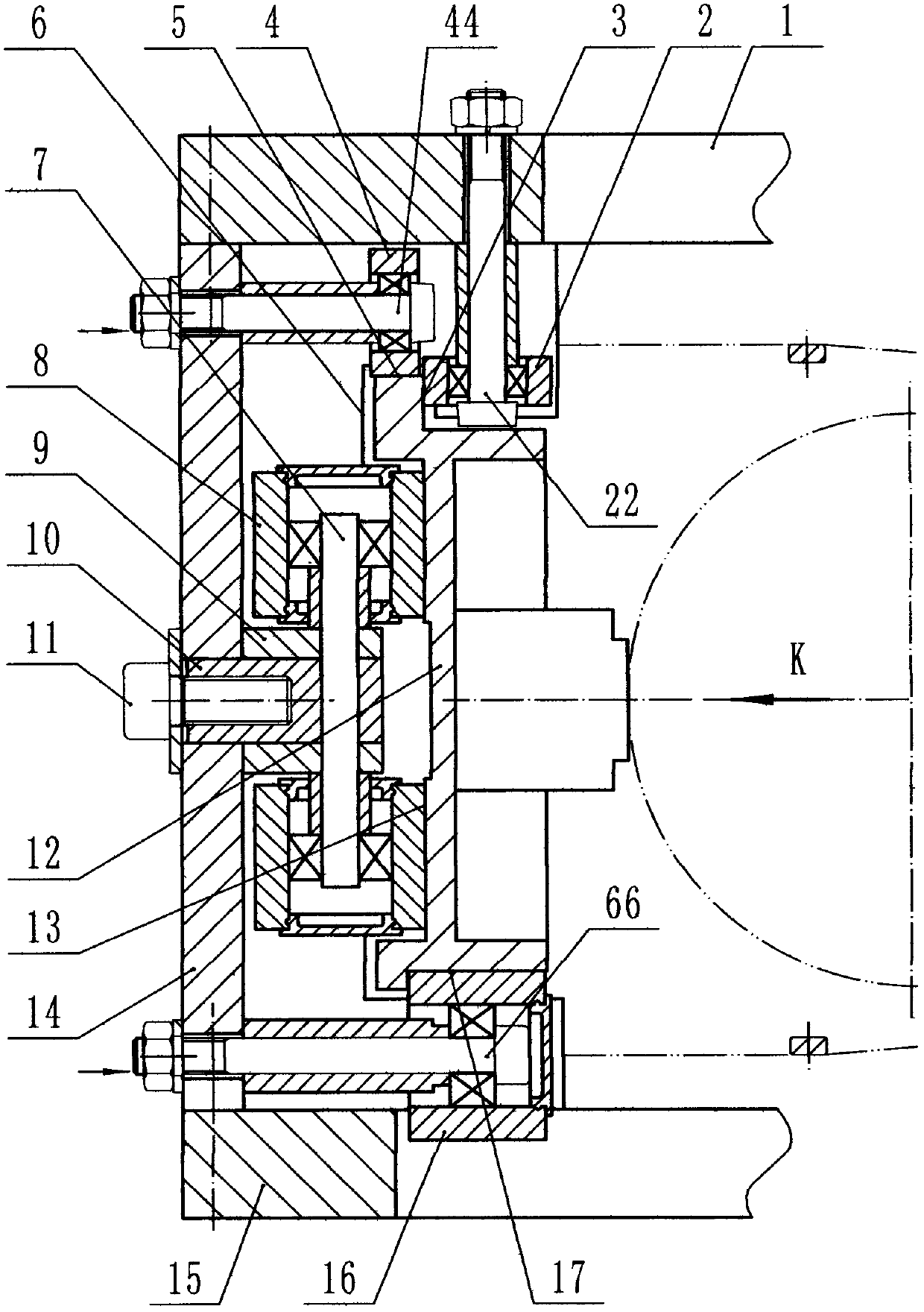
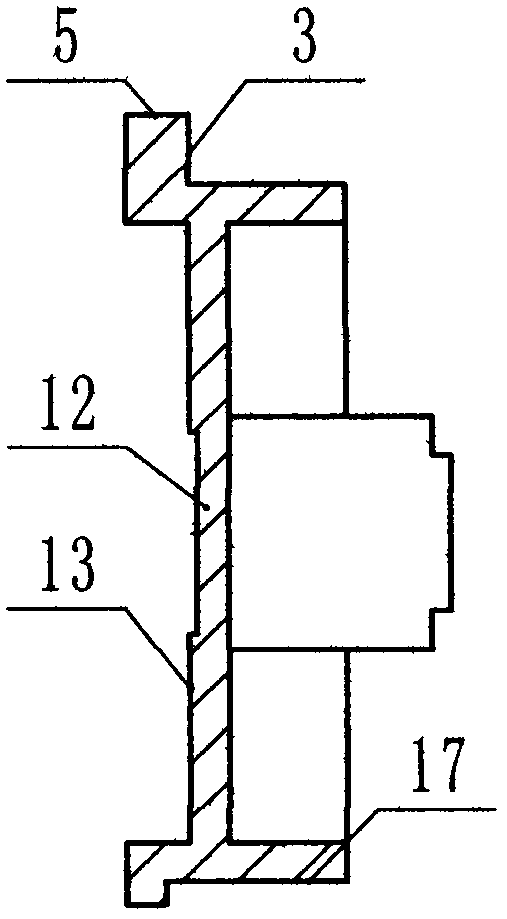
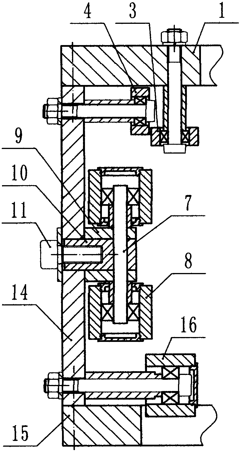
[0024] Such as Figure 1-4 As shown, the shuttle track pair of the small six-shuttle plastic circular loom includes an upper door ring (1), a lower door ring (15), and 6 shuttles (12), and also includes a ring that is arranged evenly along the circumference between the upper door ring and the lower door ring. 36 columns (14), 36 rollers A (2) on the upper door ring and roller B (4), roller C (8) and roller D (16) on the column are the cross sections of the rectangle. There are corresponding raceway A(3), raceway B(5), raceway C(13) and raceway D(17), respectively rolling and cooperating with rollers A, B, C and D to form a pair of shuttle running tracks, The axes of roller A(2) and roller C(8) are perpendicular to and coplanar with the axes of roller B(4) and roller D(16), and the vertical direction of the shuttle is controlled by rollers B(4) and D(16). Constraints, the radial direction is constrained by rollers A(2) and C(8).
[0025] The roller B (4) is located on the upp...
PUM
 Abstract
Description
Claims
Application Information