[0034] The technical solutions in the embodiments of the present invention will be clearly and completely described below in conjunction with the accompanying drawings in the embodiments of the present invention. Obviously, the described embodiments are only a part of the embodiments of the present invention, rather than all the embodiments. Based on the embodiments of the present invention, all other embodiments obtained by those of ordinary skill in the art without creative work shall fall within the protection scope of the present invention.
[0035] It should be noted that if there is a directional indication (such as up, down, left, right, front, back...) in the embodiment of the present invention, the directional indication is only used to explain that it is in a specific posture (as shown in the drawings). If the specific posture changes, the relative positional relationship, movement, etc. of the components below will also change the directional indication accordingly.
[0036] In addition, if there are descriptions involving "first", "second", etc. in the embodiments of the present invention, the descriptions of "first", "second", etc. are only used for descriptive purposes, and cannot be understood as instructions or implications Its relative importance or implicitly indicates the number of technical features indicated. Therefore, the features defined with "first" and "second" may explicitly or implicitly include at least one of the features. In addition, the meaning of "and/or" in the full text includes three parallel schemes. Taking "A and/or B" as an example, it includes scheme A, scheme B, or schemes that meet both A and B. In addition, the technical solutions between the various embodiments can be combined with each other, but they must be based on what can be achieved by those of ordinary skill in the art. When the combination of technical solutions is contradictory or cannot be achieved, it should be considered that such a combination of technical solutions does not exist. , Is not within the protection scope of the present invention.
[0037] In the normal driving process of a car, there will be different postures such as climbing, downhill, and sideways. The oil is in a liquid state. No matter what state the car is driving, the oil level is always level. The oil pan needs to be based on actual conditions. The worst conditions are designed for the boundary. Usually the oil pan is designed with the car’s maximum tilting attitude of 30° in eight directions: forward, rear, left, right, left front, right front, left rear, and right rear. The oil suction port, the suction port must always be below the lubricating oil level (including the limit of the car tilting 30° in eight directions) to ensure that the lubricating oil is sucked into the engine lubricating passage. Therefore, the design of the oil pan needs to ensure that it stores as much oil as possible. When the oil pan is tilted, the oil level must exceed the oil suction port.
[0038] In order to solve this problem, the existing oil sump adopts a method to increase the depth of the oil sump while reducing the position of the oil suction port, which causes the size of the engine to become larger, which in turn causes the engine to interfere in the layout of the vehicle or even the vehicle cannot match. problem.
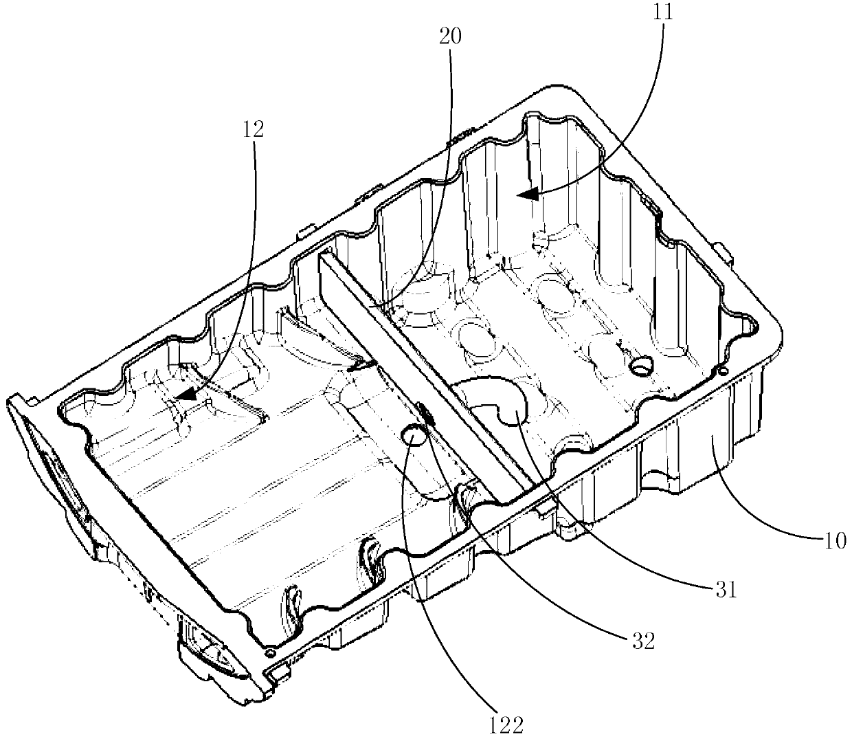
[0039] See figure 1 , Is an embodiment of the oil pan proposed by the present invention. In this embodiment, the oil pan includes a housing 10, an oil baffle 20 and a one-way component, wherein the housing 10 is the oil pan body, It has a chamber. The oil baffle 20 is arranged in the chamber extending in the vertical direction. The oil baffle 20 is used to divide the chamber into a first chamber 11 and a second chamber 12, and the first chamber 11 is used for Corresponding to the oil suction port, a one-way conduction component is provided on the oil baffle plate 20 for one-way conduction through the first chamber 11 and the second chamber 12, and the conduction flow direction of the one-way conduction component is the oil flow from the second chamber 12 First chamber 11.
[0040] In this embodiment, an oil baffle 20 is provided in the housing 10, that is, the oil pan. When the car is tilted, the oil baffle 20 can always collect the oil in the oil pan around the oil suction port. Keep the surface above the oil suction port. This design can reduce the volume of the oil pan, facilitate the layout of the entire vehicle of the engine, and improve the production efficiency of the vehicle. At the same time, during the operation of the engine, the organic oil is continuously drained from the engine parts. In the oil pan, even when the car is inclined at a large angle, the oil in the first chamber 11 may pass the oil baffle 20 and flow to the second chamber 12. Therefore, the oil baffle 20 is also provided with a one-way guide. The components allow the oil to flow from the second chamber 12 to the first chamber 11, so that the oil is concentrated in the first chamber 11 as much as possible.
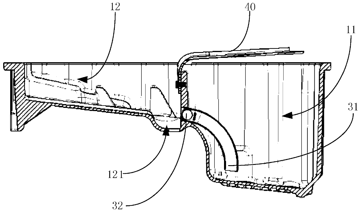
[0041] Further, see figure 2 In this embodiment, the bottom wall of the second chamber 12 is inclined upward, and the lower end is connected with the bottom wall of the first chamber 11 to enhance the flow of oil from the second chamber 12 to the first chamber 11. .
[0042] Further, the bottom wall of the second chamber 12 is provided above the bottom wall of the first chamber 11, and the lower end of the bottom wall of the second chamber 12 extends downward to connect with the bottom wall of the first chamber 11, reducing The volume of the second chamber 12 is reduced, thereby further reducing the overall volume of the oil pan.
[0043] Further, see Figure 1-Figure 2 , The first bottom wall is recessed down near the oil baffle 20 to form a deposition groove 121. The oil that drains from above the crankcase into the oil pan often includes metal chips, sludge and other impurities, among which the heavier impurities are The deposit can be accumulated in the deposit tank 121, so that the cleaner engine oil flows back to the first chamber 11 through the unidirectional conducting component.
[0044] Furthermore, a magnetic member 122 is provided in the deposition tank 121 to absorb metal debris and improve the cleanliness of the engine oil.
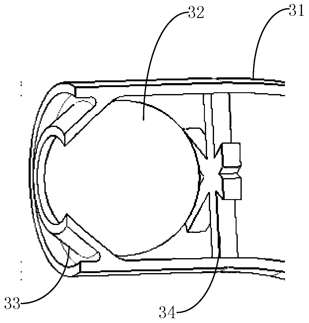
[0045] Specifically, see Figure 1-Figure 4 The one-way guide assembly includes a pipe 31, a tapered retaining ring 33, a ball core 32 and a limiting plate 34. The bottom of the oil baffle plate 20 is provided with a mounting hole corresponding to the pipe 31. The pipe 31 includes a guide set at the mounting hole. The through end and the free end extending into the first cavity 11, the tapered retaining ring 33 is provided at the conducting end, the tapered retaining ring 33 is provided with a through hole, and the small end of the tapered surface faces the first cavity 11, The spherical core 32 is provided on the tapered surface of the tapered retaining ring 33. The spherical core 32 has a blocking position abutting against the tapered surface and a conduction position away from the tapered surface. The limiting plate 34 is provided at the conduction end, The limiting plate 34 has a plurality of leakage holes 341 for blocking the core 32 and allowing oil to pass through.
[0046] Through the implementation of the above device, a one-way flow of oil from the second chamber 12 to the first chamber 11 can be realized, so that as much oil as possible is concentrated in the first chamber 11, and its structure is simple, low in cost, and convenient Manufacturing installation.
[0047] Further, the limiting plate 34 is arranged in a cross shape or a rice shape.
[0048] In this embodiment, the conduit 31 may extend to the bottom of the first chamber 11 to help the small amount of impurities remaining in the returning oil to settle at the bottom.
[0049] Further, see figure 2 with Figure 5 In this embodiment, the upper end of the oil baffle 20 is provided with a baffle 40, the baffle 40 is obliquely arranged above the first chamber 11, and the upper end is located above the first chamber 11, and the lower end is connected to The upper ends of the oil baffle 20 are connected.
[0050] The baffle 40 can protect the first chamber 11 so that the return oil of the engine can directly flow into the second chamber 12, and then flow back to the first chamber 11 after passing through the sedimentation tank 121, which improves the cleanliness of the engine oil.
[0051] Further, in an embodiment of the deflector 40, the side edge and upper end surface of the deflector 40 are provided with a plurality of convex edges 41 protruding upward to form a plurality of drainage grooves 42 to improve the drainage effect.
[0052] In another embodiment of the baffle plate 40, the baffle plate 40 is provided with a plurality of oil passage holes 43 near the oil baffle plate 20, because the oil in the second chamber 12 is returned to the second chamber through the one-way guide assembly. The flow rate of the chamber 11 is small, so that the return speed is slow. Therefore, the oil hole 43 can be directly provided on the deflector 40, so that the oil drained from the engine can directly enter the first chamber 11, in order not to affect the oil flow For the fluidity of the deflector 40, the oil passage hole is opened near the oil baffle 20.
[0053] See Figure 5 Obviously, the above two embodiments of the guide plate 40 can be implemented at the same time, and the side edge of the oil passage 43 can also be provided with a convex edge 41 to form the drainage groove 42.
[0054] Furthermore, the deflector 40 is detachably installed on the oil baffle. In this embodiment, the deflector 40 is fixed on the oil baffle 20 by bolts, which is convenient for installation and maintenance.
[0055] The above are only the preferred embodiments of the present invention, and do not limit the scope of the present invention. Under the inventive concept of the present invention, equivalent structural transformations made by using the contents of the description and drawings of the present invention, or direct/indirect use Other related technical fields are included in the scope of patent protection of the present invention.