Cam shaft

A camshaft and cam technology, which is applied to cams, shafts, couplings, etc., can solve the problems of low camshaft utilization, increased cost, and cam wear.

Inactive Publication Date: 2019-09-27
C&U CO LTD +1
View PDF10 Cites 2 Cited by
  • Summary
  • Abstract
  • Description
  • Claims
  • Application Information

AI Technical Summary

Problems solved by technology

[0002] The camshaft is a commonly used component. The camshaft is generally composed of a cam formed on a shaft. The cam of the camshaft will bear a certain load force during use. After bearing the load force, the cam is often easy to produce wear or damage, but most of the existing camshafts are integrated with the cam and the support shaft. When the cam is worn or damaged, the entire camshaft needs to be replaced, which leads to an increase in cost and a low utilization rate of the camshaft. Low

Method used


Image

  • Cam shaft
  • Cam shaft
  • Cam shaft

Examples


Embodiment Construction

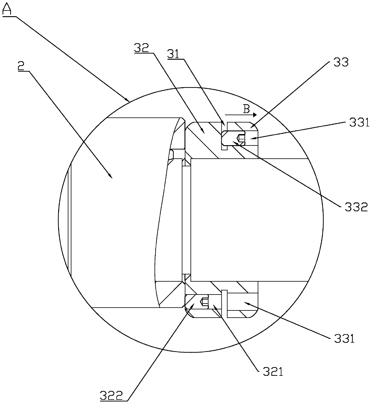
[0016] image 3 The direction of the middle arrow B is the direction of the reaction force on the second fastening block 33

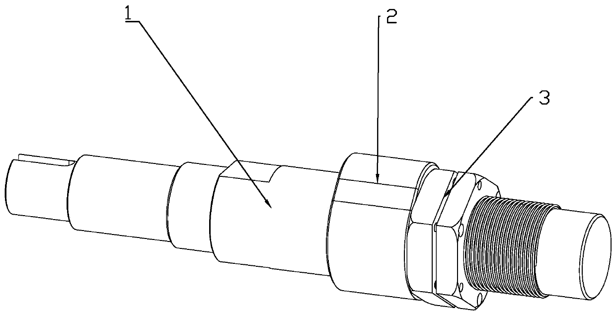
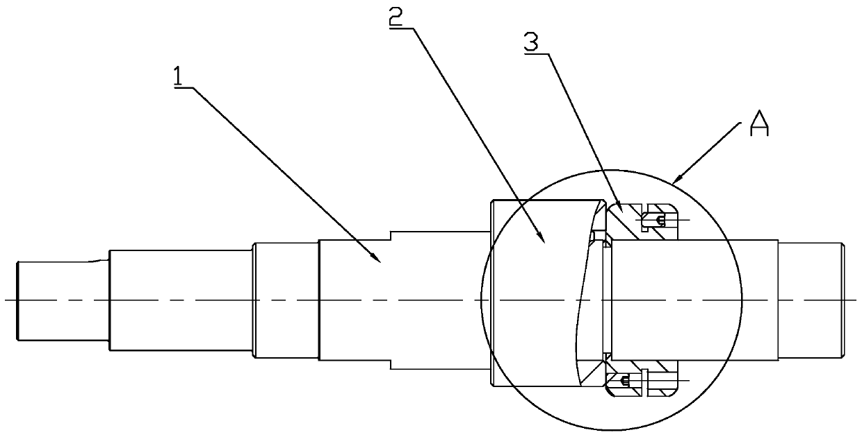
[0017] Depend on Figure 1 to Figure 6 It can be seen that the present invention discloses a camshaft, which includes a support shaft 1 and a cam sleeve 2. The support shaft 1 includes a threaded section 11, a cam installation section 12, and an interference section 13 arranged in sequence. The interference section 13 and the The junction of the cam installation section 12 is formed with a conflicting step 14, the cam sleeve 2 is movably sleeved on the cam installation section 12, the threaded section 11 is screwed with a fastening nut 3, one end of the cam sleeve 2 is in contact with the The step 14 is in conflict, and the other end is in conflict with the fastening nut 3 to realize the fixing of the cam sleeve 2 on the support shaft 1 . The cam sleeve 2 is movably sleeved on the support shaft 1, and the fastening nut 3 is screwed into the threaded s...


PUM


Abstract

The invention discloses a cam shaft. The cam shaft comprises a supporting shaft and a cam sleeve, wherein the supporting shaft comprises a threaded section, a cam mounting section and an abutting section which are sequentially arranged; an abutting step is formed at the joint of the abutting section and the cam mounting section, the cam sleeve movably sleeves the cam mounting section, a fastening nut is screwed on the threaded section, one end of the cam sleeve abuts against the abutting step, and the other end of the cam sleeve abuts against the fastening nut to realize fixation of the cam sleeve on the supporting shaft. A detachable cam structure is adopted by the cam shaft, the cam is convenient to detach, the cam is stable in mounting, and it is guaranteed that the cam cannot fall off when the cam is operated.

Description

technical field [0001] The invention relates to a camshaft. Background technique [0002] The camshaft is a commonly used component. The camshaft is generally composed of a cam formed on a shaft. The cam of the camshaft will bear a certain load force during use. After bearing the load force, the cam is often easy to produce wear or damage, but most of the existing camshafts are integrated with the cam and the support shaft. When the cam is worn or damaged, the entire camshaft needs to be replaced, which leads to an increase in cost and a low utilization rate of the camshaft. Low. Contents of the invention [0003] Aiming at the deficiencies of the prior art, the present invention provides a camshaft, which adopts a detachable cam structure, the cam is easy to disassemble, and the cam is installed stably, which ensures that the cam will not fall during operation. [0004] The present invention provides a camshaft, which includes a support shaft and a cam sleeve. The suppo...

Claims


Application Information

Patent Timeline
Patent Type & Authority Applications(China)
IPC IPC(8): F16C3/02F16H53/02F16D1/08
CPCF16C3/02F16D1/08F16H53/02
Inventor 张亚飞
Owner C&U CO LTD
Why Eureka
Try Eureka