Ultra-large gantry type automatic welding robot

An automatic welding, gantry-type technology, applied in welding equipment, auxiliary welding equipment, welding/cutting auxiliary equipment, etc., can solve the problems of easy adjustment by non-professional operators, shaking of the operating head, and inconvenience of the machine, and achieve the solution of shaking and instability , Good operation effect and stable operation effect

Pending Publication Date: 2019-10-01
菏泽京九特种汽车有限公司
View PDF5 Cites 1 Cited by
  • Summary
  • Abstract
  • Description
  • Claims
  • Application Information

AI Technical Summary

Problems solved by technology

[0003] The purpose of the present invention is to provide a super-large gantry-type automatic welding robot to solve the above-mentioned background technology that the existing welding robot is inconvenient to adjust the position of the operating panel when in use, and it is inconvenient to replace the operating panel when using it for a long time , the sliding operation of the operating head for a long time will cause the operating head to shake, which will affect the operation effect of the operating head. When the operator is not operating, the operator is not next to the machine. It is easy for non-professional operators to adjust the machine and it is not convenient for professionals to observe.

Method used


Image

  • Ultra-large gantry type automatic welding robot
  • Ultra-large gantry type automatic welding robot
  • Ultra-large gantry type automatic welding robot

Examples


Embodiment Construction

[0022] The following will clearly and completely describe the technical solutions in the embodiments of the present invention with reference to the accompanying drawings in the embodiments of the present invention. Obviously, the described embodiments are only some, not all, embodiments of the present invention. Based on the embodiments of the present invention, all other embodiments obtained by persons of ordinary skill in the art without making creative efforts belong to the protection scope of the present invention.

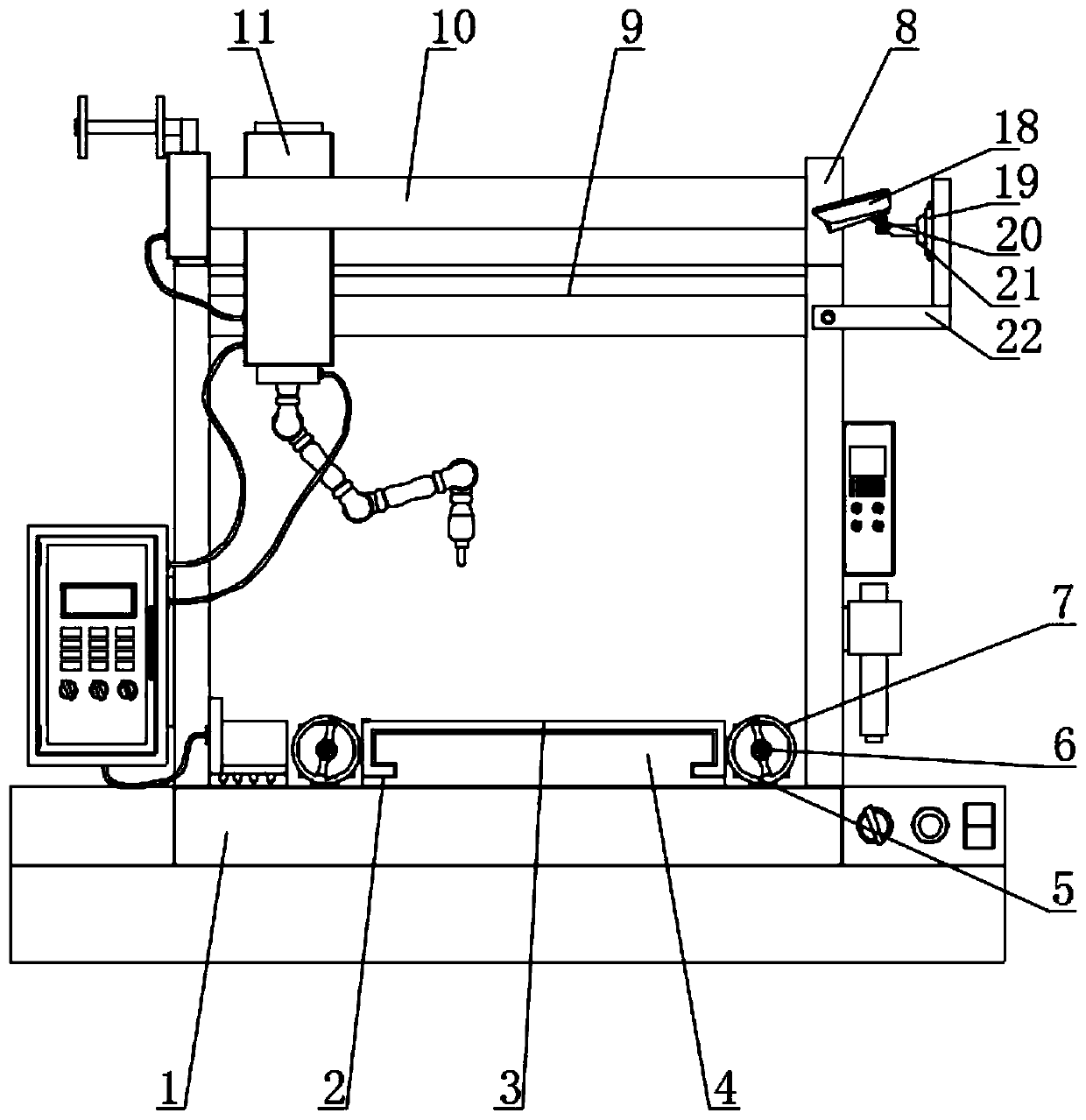
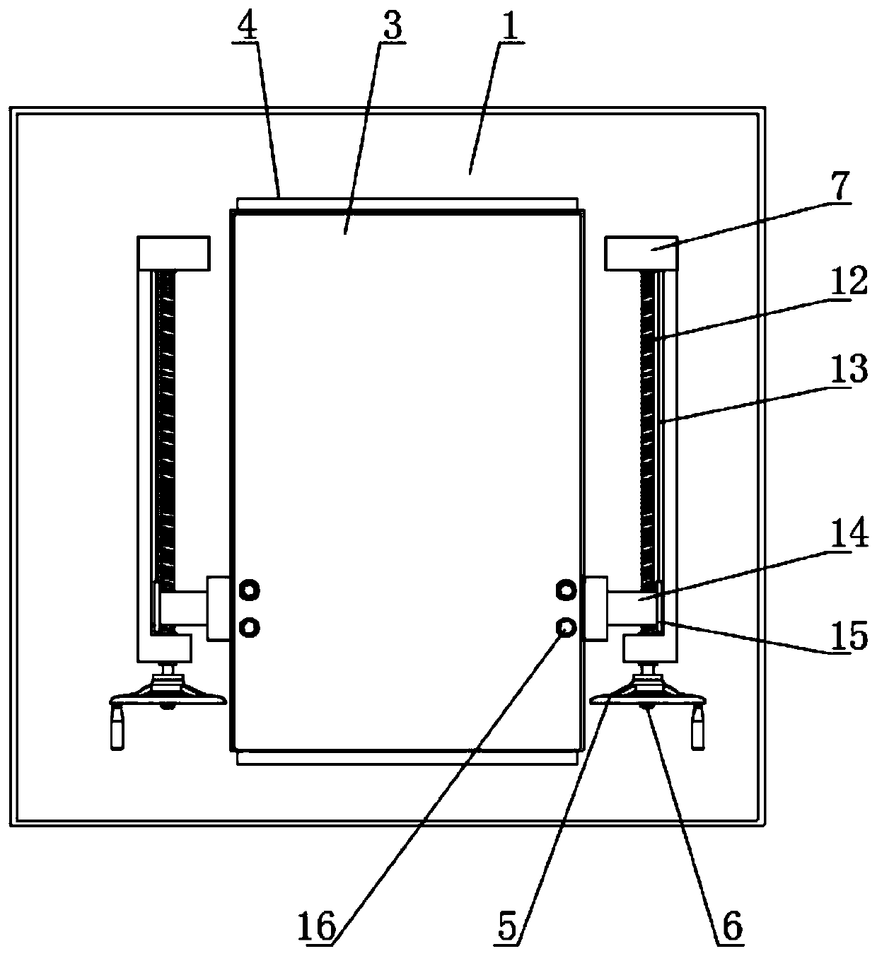
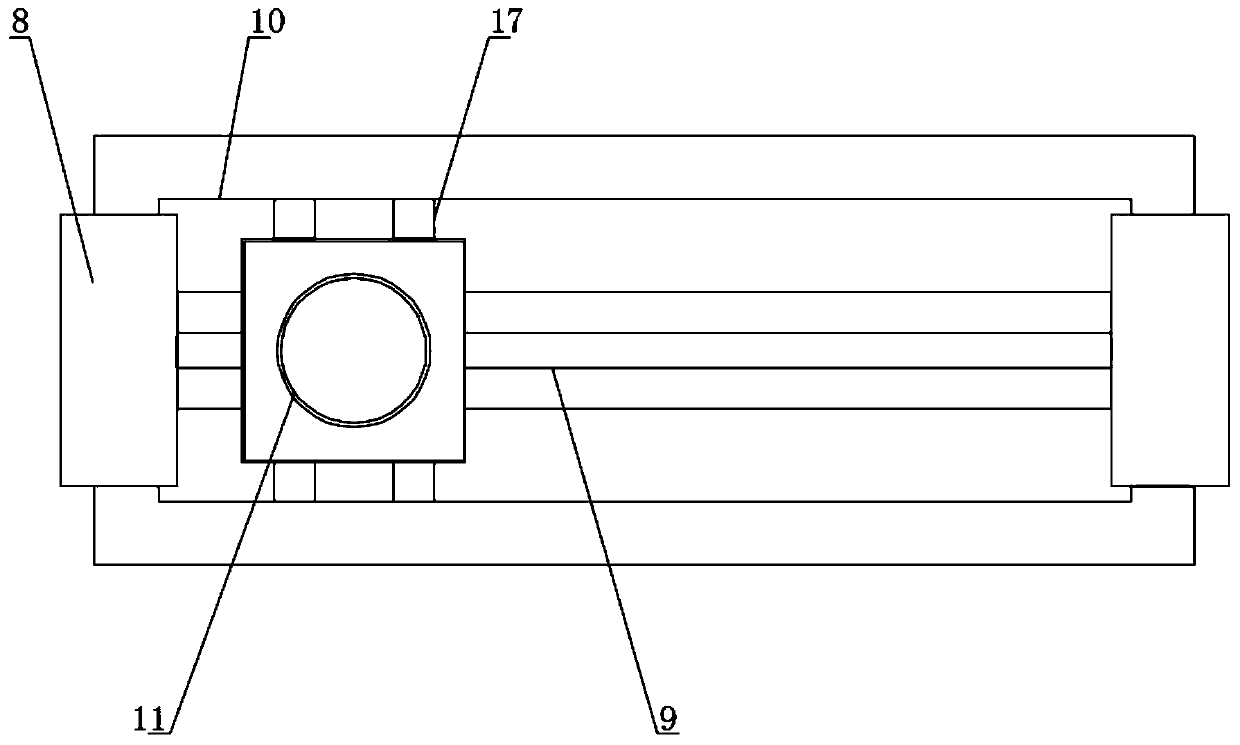
[0023] see figure 1 , figure 2 , image 3 , Figure 4 and Figure 5 , the present invention provides a technical solution: a super-large gantry type automatic welding robot, including a second base 1, the two ends of the upper surface of the second base 1 are welded and fixed with support stands 8, and the two support stands 8 The joint is welded and fixed with a support horizontal plate 9, the outer surface of the support horizontal plate 9 is slidably c...


PUM


Abstract

The invention discloses an ultra-large gantry type automatic welding robot. The robot comprises a second base, wherein two ends of the upper surface of the second base are fixedly welded to a supporting vertical frames; a supporting transverse plate is fixedly welded at the joint of the two supporting vertical frames; an operating head is slidably connected with the outer surface of the supportingtransverse plate; and a base plate is fixedly welded at the middle of the upper surface of the second base, and a first sliding groove is formed in each side of the base plate. Due to the fact that alead screw is designed in a connecting base and a connecting head is designed on the outer surface of the lead screw, the problem that the welding robot adjusts the position of an operating plate inconveniently during use is avoided, meanwhile, the operating plate is inconvenient to replace for a long time and a threaded rod can be driven to rotate by holding a hand wheel; the threaded rod rotates to enable the lead screw to rotate in the connecting base by a rotating shaft and therefore the connecting head is finely adjusted on the outer surface of the lead screw; and when replacement is carried out, disassembly and replacement can be carried out in the same operation, and the problems of inconvenient fine adjustment of the position of the operating plate and replacement of the operatingplate are solved.

Description

technical field [0001] The invention belongs to the technical field of welding robots, and in particular relates to an extra-large gantry type automatic welding robot. Background technique [0002] Existing welding robots are industrial robots engaged in welding (including cutting and spraying). According to the definition of the International Organization for Standardization (ISO) that an industrial robot belongs to a standard welding robot, an industrial robot is a multipurpose, reprogrammable, automatic control manipulator with three or more programmable axes, used in the field of industrial automation . In order to adapt to different purposes; the existing welding robot is inconvenient to adjust the position of the operation panel during use, and it is not convenient to replace the operation panel after long-term use. The sliding operation of the operation head will cause the operation head to shake during long-term use, affecting The operation effect of the operation ...

Claims


Application Information

Patent Timeline
Patent Type & Authority Applications(China)
IPC IPC(8): B23K37/00B23K37/02
CPCB23K37/00B23K37/0252
Inventor 魏秋东孙从义魏中保
Owner 菏泽京九特种汽车有限公司
Why Eureka
Try Eureka