Two-phase flow power heat pipe system

A fluid power, two-phase flow technology, applied in the field of heat exchange, can solve the problems of insufficient circulating power and incomplete gas-liquid separation, reduce the limitations of use conditions, solve the problems of high and low position difference and conveying distance, and improve heat exchange efficiency. Effect

Active Publication Date: 2012-11-14
BEIJING FULLLINK OREITH TECH CO LTD
View PDF4 Cites 11 Cited by
  • Summary
  • Abstract
  • Description
  • Claims
  • Application Information

AI Technical Summary

Problems solved by technology

[0006] A new type of heat pipe heat exchange device technology provided by the present invention—a two-phase flow power heat pipe system is to solve the problems of incomplete gas-liquid separation and insufficient circulation power existing in the current power heat pipe work

Method used


Image

  • Two-phase flow power heat pipe system
  • Two-phase flow power heat pipe system
  • Two-phase flow power heat pipe system

Examples


Embodiment 1

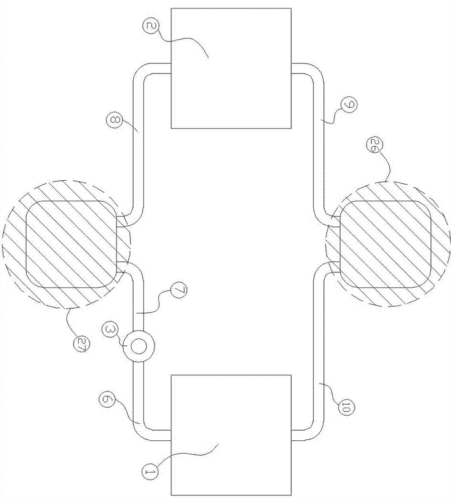
[0030] This embodiment is the workflow of the first implementation mode, such as figure 2 As shown, the condenser (1), circulation pump (3), one-way two-phase flow stabilizer two (30), evaporator (2) and one-way two-phase flow stabilizer one (28) are connected in the above order through the connecting pipes It is connected as a whole to form a one-way two-phase flow dynamic heat pipe circulation system. When the system is working, the condenser (1) is in contact with a low-temperature heat source, and the gaseous working medium is cooled by the low-temperature heat source in the condenser (1) and condenses into a liquid. And release heat, the liquid working medium formed by condensation is driven by the delivery pump (3), and they enter the one-way two-phase current stabilizer two (30 ) of the gas-liquid separator two (5), the gas-liquid two-phase flow intermediate working medium is separated in the gas-liquid separator two (5) according to their respective physical propertie...

Embodiment 2

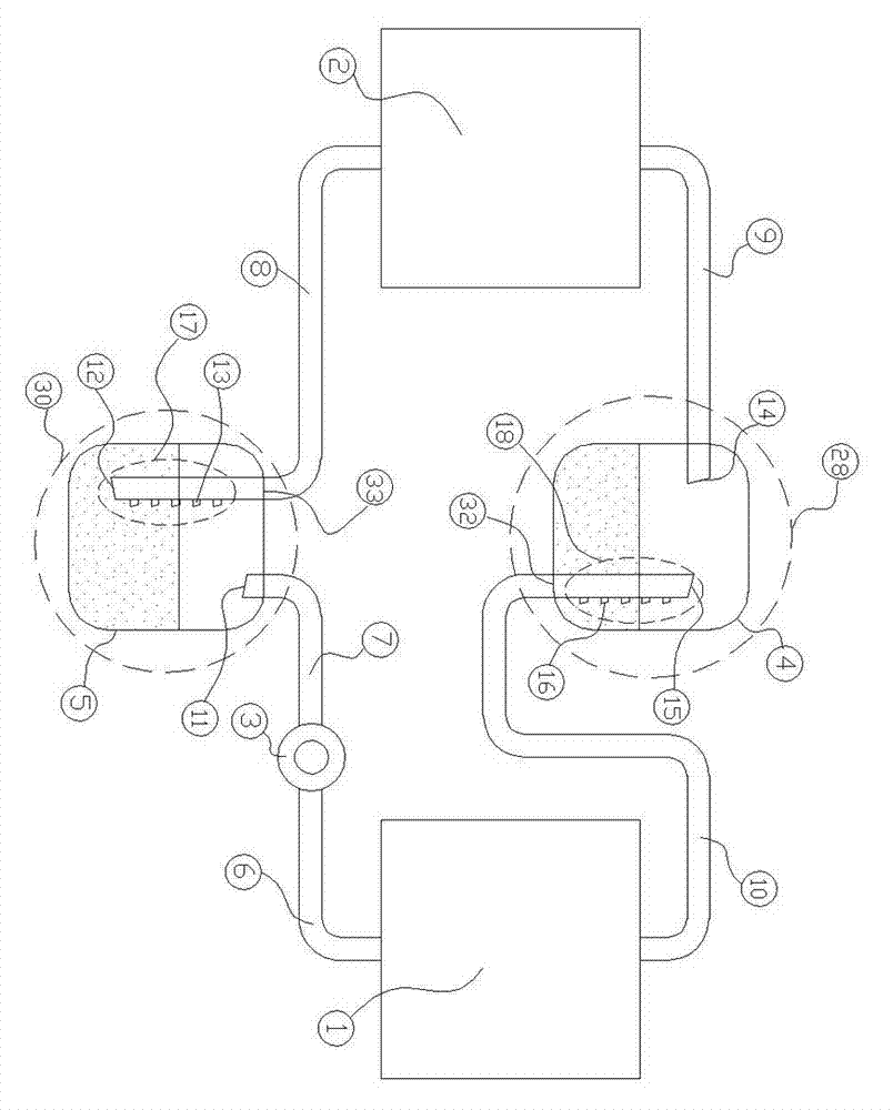
[0035] This embodiment is the workflow of the second second implementation mode, such as image 3 As shown, the one-way two-phase flow stabilizer two (30) is located between the condenser (1) and the circulating pump (3), and the evaporator (2) and the circulating pump (3) are directly connected by the two-phase The flow input pipe (8) is connected, so that the condenser (1), one-way two-phase flow regulator two (30), circulation pump (3), evaporator (2) and one-way two-phase flow regulator one (28) The connecting pipes are connected as a whole in the above order to form a unidirectional two-phase flow power heat pipe circulation system.

[0036] When the system is working, the circulating pump (3) extracts a certain proportion of two-phase flow working medium from the gas-liquid separator two (5) of the one-way two-phase flow stabilizer two (30), so that the liquid intermediate medium passes through the return liquid Port 1 (12) and a small amount of gaseous intermediate med...

Embodiment 3

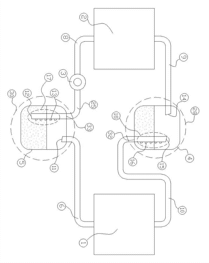
[0032] When the temperature difference between the high-temperature environment end and the low-temperature environment end does not reach the environment required by the system, the circuit control element turns off the circulation pump (3) through the signal sent by the temperature detection part, and the system is in a stopped state; when the high-temperature environment end is more than When the temperature of the low-temperature environment end exceeds a certain value, the temperature detection part in the circuit control detects a signal, and then the control circuit controls the circulation pump (3) to automatically turn on, and the whole system is in a normal operating state.

[0033] The working process of the system is an ideal working state. It can only bring high-temperature energy to low-temperature places, and cannot move low-temperature energy to high-temperature places. After the system is installed, the work of the condenser (1) and the evaporator (2) The prope...


PUM


Abstract

The invention discloses a two-phase flow power heat pipe system which is mainly formed by a condenser, an evaporator, a first two-phase flow stabilizer, a second two-phase flow stabilizer, a circulating pump and a circuit control element. Two heat exchanger, i.e. the condenser and the evaporator, aim to implement energy transportation; the first two-phase flow stabilizer and the second two-phase flow stabilizer have the functions of firstly implementing gas-liquid separation and slow storage of a working medium and then reasonably distributing the flow proportions of a liquid working medium and a gas working medium in a circulating loop so as to form stable working medium two-phase flow in the circulating loop and improving the efficiency of a heat pipe; and the circuit control element is used for controlling the operation state of the system. According to the power heat pipe system, by the design of the two two-phase flow stabilizers and the circulating pump, the problems of incomplete gas-liquid separation and insufficient circulating power in heat-pipe heat exchange equipment are solved and the working efficiency and the practicality of the heat pipe are improved; and the adopted integral system device has simple structure and is environmental-friendly.

Description

technical field [0001] The invention relates to the technical field of heat exchange, in particular to a novel heat pipe heat exchange system, in particular to a split-type two-phase flow heat pipe device with a circulation pump. Background technique [0002] As a high-efficiency heat transfer element, heat pipes are increasingly used in engineering. Heat pipes are not only widely used in waste heat recovery, cooling of electronic components, etc., but also in the field of traditional heat and mass transfer equipment, heat pipes have a tendency to replace circulating water, circulating oil and steam for heat transfer. When the ambient temperature is low, the heat pipe can also replace the current air-conditioning system as a cooling and temperature control element for electronic equipment, power equipment, computer rooms, and communication rooms. [0003] Heat pipes have a variety of structural forms, and there are also a variety of classification methods. Classified accor...

Claims


Application Information

Patent Timeline
Patent Type & Authority Applications(China)
IPC IPC(8): F28D15/02
Inventor 祝长宇丁式平
Owner BEIJING FULLLINK OREITH TECH CO LTD
Why Eureka
Try Eureka