
Camera adjusting device based on parallel mechanism two-degree-of-freedom redundant driving

A technology for adjusting devices and degrees of freedom. It is applied in the direction of supporting machines, mechanical equipment, and machine platforms/supports. It can solve the problems of cumulative error of the drive shaft and decrease in overall motion accuracy, and achieves less dynamic error, easy adjustment, and high precision. Adjust the effect of camera pose

Active Publication Date: 2019-10-01
XI'AN INST OF OPTICS & FINE MECHANICS - CHINESE ACAD OF SCI
View PDF7 Cites 3 Cited by
  • Summary
  • Abstract
  • Description
  • Claims
  • Application Information

AI Technical Summary

Problems solved by technology

[0003] The purpose of the present invention is to solve the problem that the cumulative error of the drive shaft in the existing camera attitude adjustment mechanism leads to the decrease of its overall motion accuracy, and to provide a camera adjustment device based on two degrees of freedom redundant drive of the parallel mechanism, which can realize two freedom high-precision attitude adjustment

Method used


Image

  • Camera adjusting device based on parallel mechanism two-degree-of-freedom redundant driving
  • Camera adjusting device based on parallel mechanism two-degree-of-freedom redundant driving
  • Camera adjusting device based on parallel mechanism two-degree-of-freedom redundant driving

Examples


Embodiment Construction

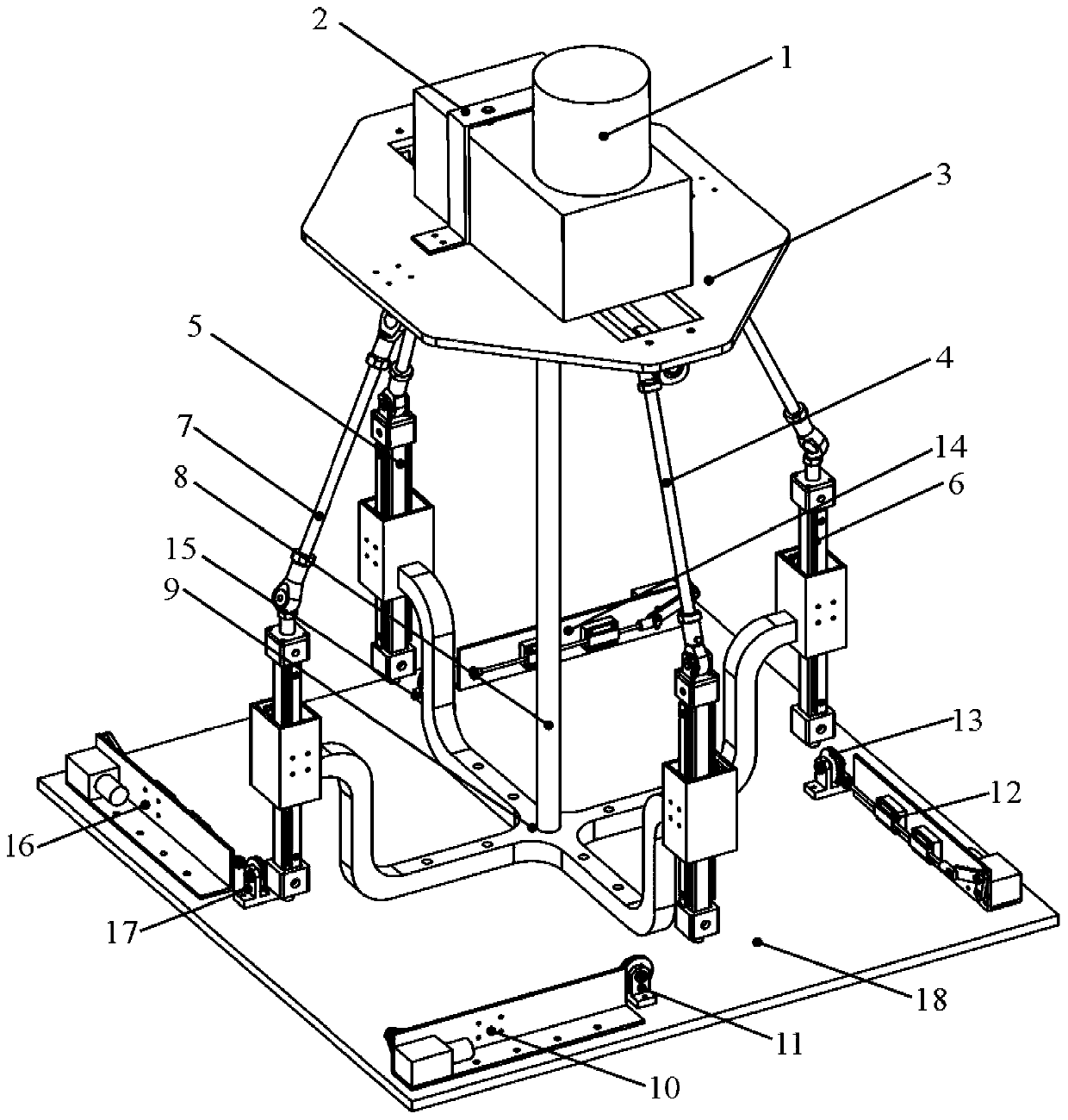
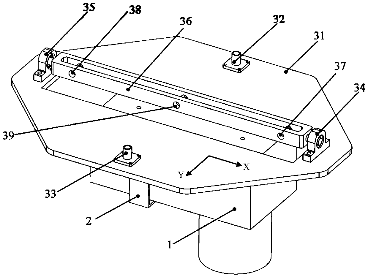
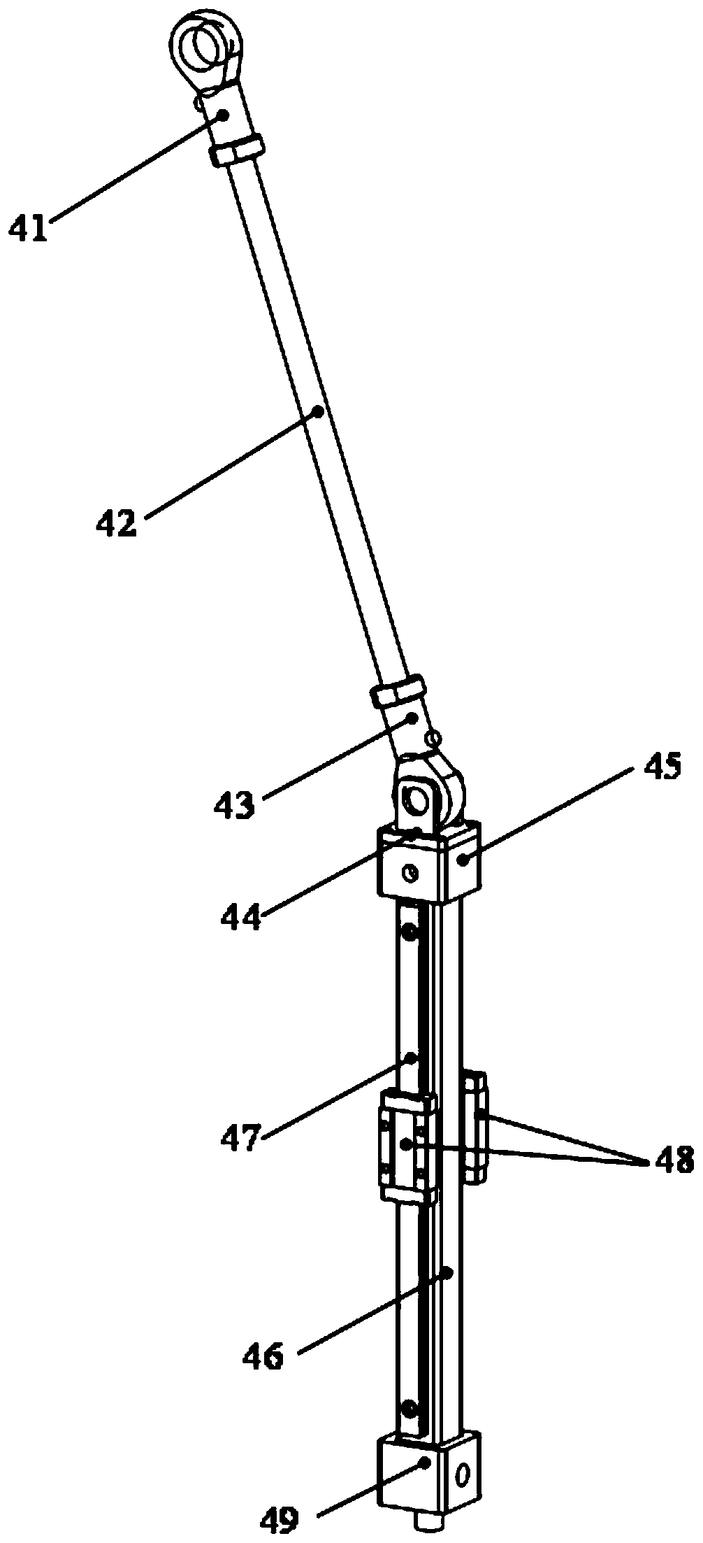
[0027] The content of the present invention will be further described in detail below in conjunction with the accompanying drawings and specific embodiments.

[0028] The invention provides a camera adjustment device based on two-degree-of-freedom redundant drive of a parallel mechanism, which can realize two-degree-of-freedom rotation of the camera, facilitate adjustment of the attitude of the camera, and realize clear shooting of a target object. In addition, according to actual application requirements, it can be used with the existing XYZ linear guide rail slide to realize 5 degrees of freedom adjustment of the camera, so as to realize large-scale push-broom shooting in three directions of XYZ, making it widely used in the field of machine vision.

[0029] Such as Figure 1 to Figure 6 As shown, the camera adjustment device based on the redundant drive of the two degrees of freedom of the parallel mechanism in the present invention includes a fixed clamp 2, a moving platfo...


PUM


Abstract

The invention relates to a camera adjusting device based on parallel mechanism two-degree-of-freedom redundant driving. The camera adjusting device is used for solving the problem that the movement precision of a mechanism is declined due to accumulative error of a driving shaft in an existing camera adjusting mechanism. In the camera adjusting device, a movable platform assembly comprises a movable platform and a rotary support, the upper surface of the movable platform is used for mounting a sealed camera, the rotary support is arranged on the lower surface of the movable platform; one end of a middle constraint branched chain is hinged to the rotary support, and the other end of the middle constraint branched chain is fixedly connected with a fixed support; the fixed support is fixedlyconnected with a mounting base plate; a first driving branched chain and a second driving branched chain are the same in structure, one ends of the first driving branched chain and the second drivingbranched chain are hinged to the rotary support, and the other ends of the first driving branched chain and the second driving branched chain and the fixed support form a sliding pair; a third drivingbranched chain and a fourth driving branched chain are the same in structure, one ends of the third driving branched chain and the fourth driving branched chain are hinged to the movable platform, and the other ends of the third driving branched chain and the fourth driving branched chain and the fixed support form a sliding pair; and a first motor assembly, a second motor assembly, a third motorassembly and a fourth motor assembly are the same in structure and are used for driving the sliding pairs to move.

Description

technical field [0001] The invention relates to a camera adjustment mechanism, in particular to a camera adjustment device based on two-degree-of-freedom redundant drive of a parallel mechanism, which can realize two-degree-of-freedom rotation of the camera, facilitate adjustment of the attitude of the camera, and realize clear shooting of a target object. Background technique [0002] When shooting with a camera, often due to its limited field of view, it is necessary to use a camera adjustment mechanism or a camera adjustment platform to adjust the camera attitude. The output motion of each front mechanism is the input of its rear mechanism, so the output motion error of each single-degree-of-freedom mechanism will accumulate to the end of the series mechanism, resulting in a decrease in the motion accuracy of the series mechanism, which in turn affects the high precision. camera pose adjustment. Contents of the invention [0003] The purpose of the present invention is...

Claims


Application Information

Patent Timeline
Patent Type & Authority Applications(China)
IPC IPC(8): F16M13/02F16M11/18G03B17/56
CPCF16M13/027F16M11/12F16M11/18
Inventor 贾昕胤李思远张兆会柯善良
Owner XI'AN INST OF OPTICS & FINE MECHANICS - CHINESE ACAD OF SCI
Learn More