Imaging optical lens

A technology of optical lens and optical total length, which is applied in the field of optical lens, can solve the problems of unreasonable setting of focal power, lens distance and lens shape, and cannot meet the problems of large aperture, ultra-thin, wide-angle, etc., and achieve good optical performance Effect

Active Publication Date: 2019-10-01
AAC OPTICS SOLUTIONS PTE LTD
View PDF6 Cites 14 Cited by
  • Summary
  • Abstract
  • Description
  • Claims
  • Application Information

AI Technical Summary

Problems solved by technology

However, with the development of technology and the increase of diversified needs of users, as the pixel area of ​​the photosensitive device continues to shrink, and the system’s requirements for imaging quality continue to increase, the six-element lens structure gradually appears in the lens design. Common Although the six-piece lens already has good optical performance, its focal power, lens spacing and lens shape settings still have certain irrationality, resulting in a lens structure that cannot meet the requirements of large aperture, large aperture, and lens shape while having good optical performance. Ultra-thin, wide-angle design requirements

Method used


Image

  • Imaging optical lens
  • Imaging optical lens
  • Imaging optical lens

Examples


no. 1 approach

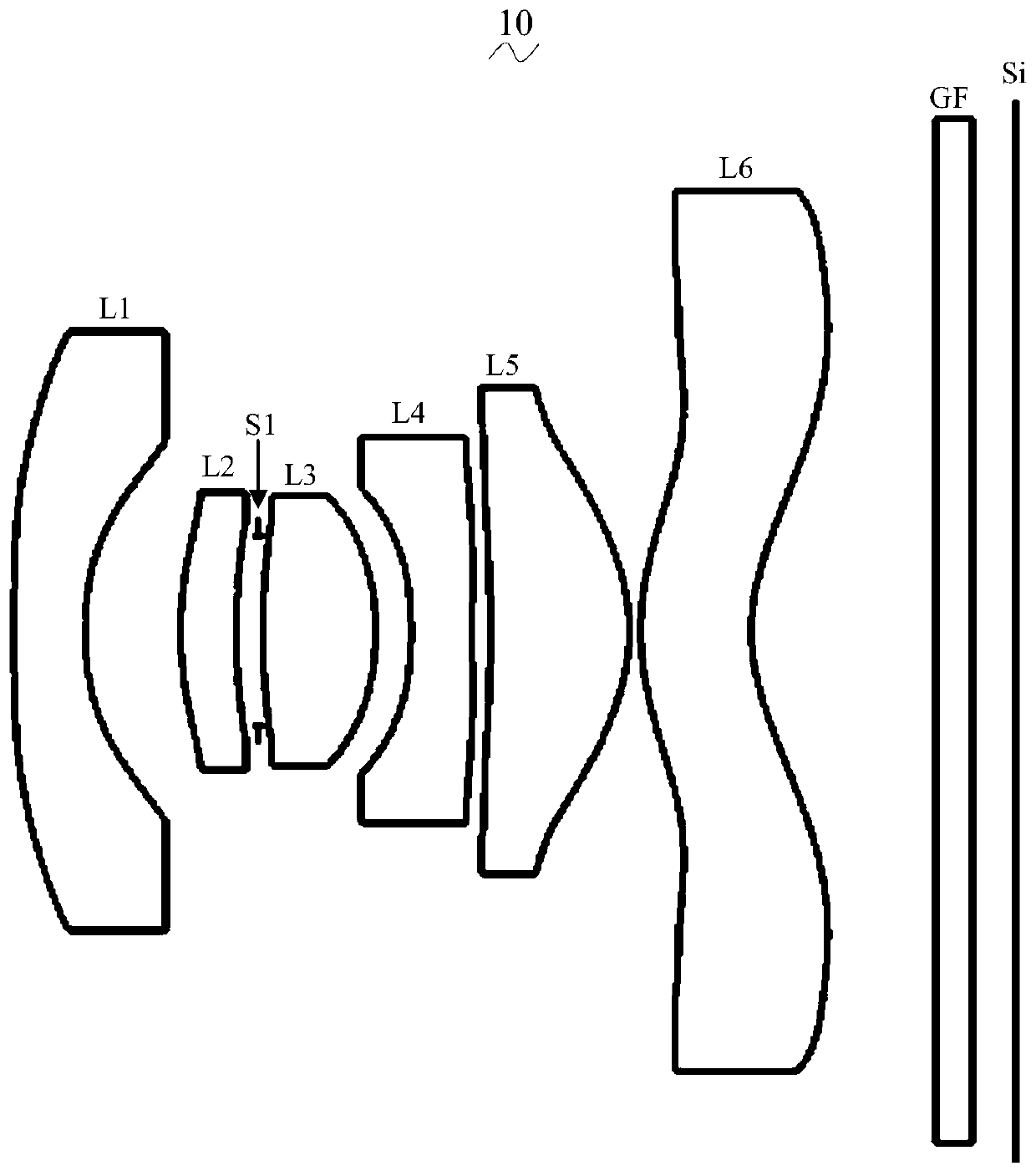
[0054] Please refer to the accompanying drawings, the present invention provides an imaging optical lens 10 . figure 1 Shown is the imaging optical lens 10 of the first embodiment of the present invention, and the imaging optical lens 10 includes six lenses. Specifically, the imaging optical lens 10 includes, from the object side to the image side in sequence: a first lens L1 with a negative refractive power, a second lens L2 with a positive refractive power, an aperture S1, and a third lens with a positive refractive power. A lens L3, a fourth lens L4 having a negative refractive power, a fifth lens L5 having a positive refractive power, and a sixth lens L6 having a negative refractive power. An optical element such as an optical filter (filter) GF may be disposed between the sixth lens L6 and the image plane Si.

[0055] In this embodiment, the overall focal length of the imaging optical lens is defined as f, the focal length of the first lens L1 is f1, and the following rela...

no. 2 approach

[0150] The second embodiment is basically the same as the first embodiment, and the meanings of symbols are the same as those of the first embodiment. For the structure of the imaging optical lens 20 of the second embodiment, please refer to Figure 5 As shown, only the differences are listed below.

[0151] Table 5 and Table 6 show design data of the imaging optical lens 20 according to the second embodiment of the present invention.

[0152] 【table 5】

[0153]

[0154] Table 6 shows the aspheric surface data of each lens in the imaging optical lens 20 according to the second embodiment of the present invention.

[0155] 【Table 6】

[0156]

[0157]

[0158] Table 7 and Table 8 show the design data of inflection point and stagnation point of each lens in the imaging optical lens 20 according to the second embodiment of the present invention.

[0159] 【Table 7】

[0160] Number of inflection points Inflection point position 1 Inflection point positio...

no. 3 approach

[0168] The third embodiment is basically the same as the first embodiment, and the meanings of symbols are the same as those of the first embodiment. For the structural form of the imaging optical lens 30 of the third embodiment, please refer to Figure 9 As shown, only the differences are listed below.

[0169] Table 9 and Table 10 show design data of the imaging optical lens 30 according to the third embodiment of the present invention.

[0170] 【Table 9】

[0171]

[0172]

[0173] Table 10 shows the aspheric surface data of each lens in the imaging optical lens 30 of the third embodiment of the present invention.

[0174] 【Table 10】

[0175]

[0176] Table 11 and Table 12 show the design data of the inflection point and the stagnation point of each lens in the imaging optical lens 30 according to the third embodiment of the present invention.

[0177] 【Table 11】

[0178] Number of inflection points Inflection point position 1 Inflection point po...


PUM


Abstract

The invention relates to the field of optical lens and discloses an imaging optical lens. The imaging optical lens successively comprises a first lens with negative refractive power, a second lens with positive refractive power, a third lens with positive refractive power, a fourth lens with negative refractive power, a five lens with positive refractive power and a sixth lens with negative refractive power from an object side to an image side, wherein the focal length of the first lens is f1; the overall focal length of the imaging optical lens is f; the on-axis thickness of the first lens isd1; the on-axis thickness of the second lens is d3; the focal length of the sixth lens is f6; f1, f, d1, d3 and f6 meet the following relation expressions: a ratio of f1 to f is greater than or equalto -3.00 and is less than or equal to -1.20, d1 / d3 is greater than or equal to 1.00 and is less than or equal to 2.00, and f6 / f is greater than or equal to -10.00 and is less than or equal to -3.00.The imaging optical lens has good optical performance; meanwhile, the large-aperture, wide-angle and ultrathin design requirements are also met.

Description

【Technical field】 [0001] The invention relates to the field of optical lenses, in particular to an imaging optical lens suitable for portable terminal devices such as smart phones and digital cameras, and imaging devices such as monitors and PC lenses. 【Background technique】 [0002] In recent years, with the rise of smart phones, the demand for miniaturized photographic lenses has been increasing, and the photosensitive devices of general photographic lenses are nothing more than photocoupled devices (Charge Coupled Device, CCD) or complementary metal oxide semiconductor devices (Complementary Metal -OxideSemiconductor Sensor, CMOS Sensor), and due to the improvement of semiconductor manufacturing process technology, the pixel size of photosensitive devices has been reduced, and today's electronic products are developing with good functions and thin, light and small appearance. Therefore, they have good Miniaturized camera lenses with image quality have become the mainstrea...

Claims


Application Information

Patent Timeline
Patent Type & Authority Applications(China)
IPC IPC(8): G02B13/00G02B13/18G02B13/06
CPCG02B13/0045G02B13/06
Inventor 孙雯
Owner AAC OPTICS SOLUTIONS PTE LTD
Why Eureka
Try Eureka