Differential pressure type profiling matrix cylinder group mechanism

A cylinder group and differential pressure technology, which is applied in the field of sanding machines, can solve problems such as uneven pressure, omission of processing areas, and low yield rate, and achieve the effects of increased adaptability, high resolution, and good effects

Inactive Publication Date: 2019-10-08
青岛威特锐智能装备有限公司
View PDF0 Cites 0 Cited by
  • Summary
  • Abstract
  • Description
  • Claims
  • Application Information

AI Technical Summary

Problems solved by technology

[0002] When the processing unit of the existing sanding machine is working, the flatness of the plate surface is often deviated due to the deformation of the workpiece. The existing processing unit has a certain compensation function, but it acts on the workpiece with a fixed pressure. In other words, the pressure is uneven, the high position is under greater pressure, and the low position is under less pressure or cannot be touched. The processing unit cannot actually perform profiling according to the deformation curvature of the workpiece, resulting in partial processing damage to the workpiece surface. Or the processing area is missing, for the workpiece processing with a large difference in the flatness of the workpiece surface, the yield rate is low, which increases the cost of the operation

Method used


Image

  • Differential pressure type profiling matrix cylinder group mechanism
  • Differential pressure type profiling matrix cylinder group mechanism
  • Differential pressure type profiling matrix cylinder group mechanism

Examples


Embodiment 1

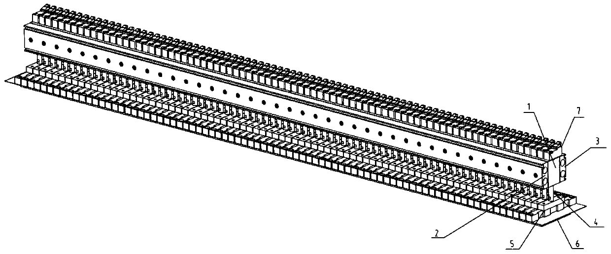
[0015] Embodiment 1, as figure 1 , 2 As shown, a pressure difference type profiling matrix cylinder group mechanism includes a matrix cylinder block 1 arranged horizontally, and a left air circuit board 2 and a right air circuit board 3 are respectively arranged on both sides of the matrix cylinder block 1. A cylinder cavity 1-1 is horizontally arranged in the cylinder body 1, and a piston column 4 is evenly arranged in the cylinder cavity 1-1, and a connecting piece 5 is provided at the end of the piston column 4, and a flexible piece is provided at the bottom of the connecting piece 5. The backing plate 6, the top of the matrix cylinder block 1 is also provided with a control valve 7 corresponding to the piston rod 4 one by one.

Embodiment 2

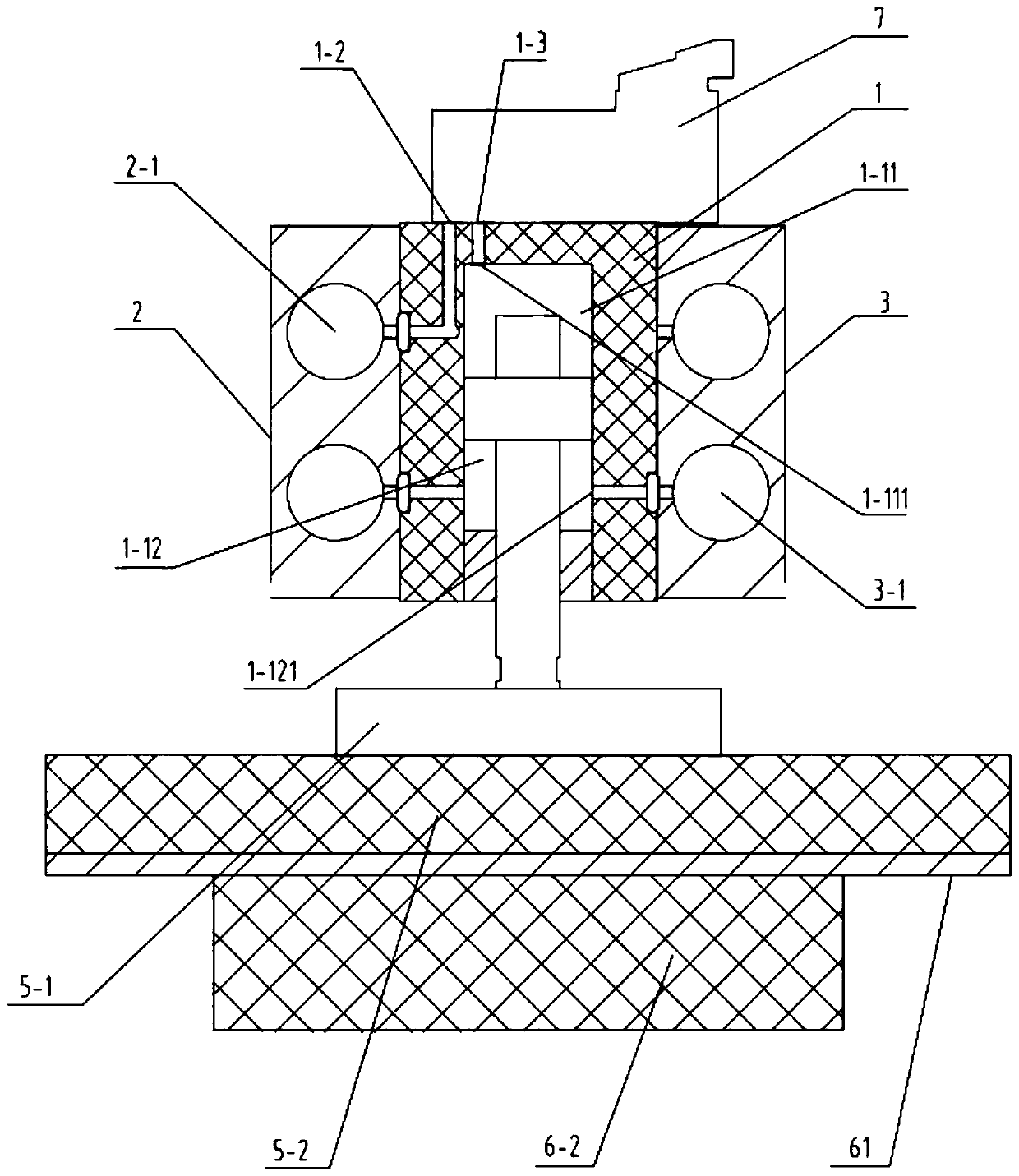
[0016] Embodiment 2, as figure 1 , 2 , 3, on the basis of Embodiment 1, the cylinder cavity 1-1 is composed of an upper air chamber 1-11 and a lower air chamber 1-12, and the piston rod 4 is formed between the upper air chamber 1-11 and the lower air chamber 1-12. The air chamber 1-12 performs reciprocating motion; the left air circuit board 2 is provided with a left air intake hole 2-1, and the top of the matrix cylinder body 1 is provided with a cylinder air intake hole 1-2 and a cylinder air outlet hole 1-3 , the upper air chamber 1-11 is provided with an upper air chamber air inlet 1-111, the right air circuit board 3 is provided with a right air inlet 3-1, and the lower air chamber 1-12 is provided with a lower air inlet chamber air intake hole 1-121; the left air intake hole 2-1 communicates with the cylinder air intake hole 1-2, the cylinder air intake hole 1-2 communicates with the control valve 7, and the control valve 7 communicates with the The air outlet hole 1-3...

Embodiment 3

[0017] Embodiment 3, as figure 1 , 2 , 3, on the basis of Embodiment 1, the connecting piece 5 comprises an aluminum block 5-1 and a plastic block 5-2, the aluminum block 5-1 is placed on top of the plastic block 5-2, and the The aluminum block 5-1 is connected with the piston rod 4.


PUM


Abstract

The invention belongs to the technical field of sanding machines, and particularly relates to a differential pressure type profiling matrix cylinder group mechanism. According to the technical schemeof the differential pressure type profiling matrix cylinder group mechanism, the resolution of a contact surface between a flexible base plate and a workpiece within a limited working size range is higher, and the purpose of precision machining is achieved. The profiling matrix cylinder group mechanism comprises a matrix cylinder block arranged horizontally, and both sides of the matrix cylinder block are provided with a left gas circuit board and a right gas circuit board separately; the matrix cylinder block is internally provided with a cylinder cavity horizontally, and piston rods are distributed in the cylinder cavity uniformly; the ends of the piston rods are provided with connecting pieces, and the flexible base plate is arranged at the bottoms of the connecting pieces; the top of the matrix cylinder block is further provided with control valves corresponding to the piston rods one by one.

Description

technical field [0001] The invention belongs to the technical field of sanding machines, and in particular relates to a pressure difference type profiling matrix cylinder group mechanism. Background technique [0002] When the processing unit of the existing sanding machine is working, the flatness of the plate surface is often deviated due to the deformation of the workpiece. The existing processing unit has a certain compensation function, but it acts on the workpiece with a fixed pressure. In other words, the pressure is uneven, the high position is under greater pressure, and the low position is under less pressure or cannot be touched. The processing unit cannot actually perform profiling according to the deformation curvature of the workpiece, resulting in partial processing damage to the workpiece surface. Or the processing area is omitted. For the processing of workpieces with large differences in the flatness of the workpiece surface, the yield rate is low, which ...

Claims


Application Information

Patent Timeline
Patent Type & Authority Applications(China)
IPC IPC(8): B24B21/18F15B15/14F15B13/02
CPCB24B21/18F15B13/02F15B15/1423F15B15/1447
Inventor 朱亚光缪鹏白洋陈钢
Owner 青岛威特锐智能装备有限公司
Why Eureka
Try Eureka