A variable servo valve, a power servo valve and a variable pump

A power valve and servo valve technology, applied in the field of hydraulic controllers, can solve the problems of difficult processing and assembly, a large number of parts, and high cost, and achieve the effects of reducing assembly difficulty and cost, adjusting power and displacement, and simplifying the structure

Active Publication Date: 2020-09-22
JIANGSU HENGLI HYDRAULIC TECH CO LTD
View PDF11 Cites 0 Cited by
  • Summary
  • Abstract
  • Description
  • Claims
  • Application Information

AI Technical Summary

Problems solved by technology

[0004] In order to solve the problems of complex structure, large number of parts, difficult processing and assembly, and high cost of the flow control device of the hydraulic pump in the prior art, the present invention proposes a variable servo valve, a power servo valve and a variable variable pump

Method used


Image

  • A variable servo valve, a power servo valve and a variable pump
  • A variable servo valve, a power servo valve and a variable pump
  • A variable servo valve, a power servo valve and a variable pump

Examples


Embodiment 1

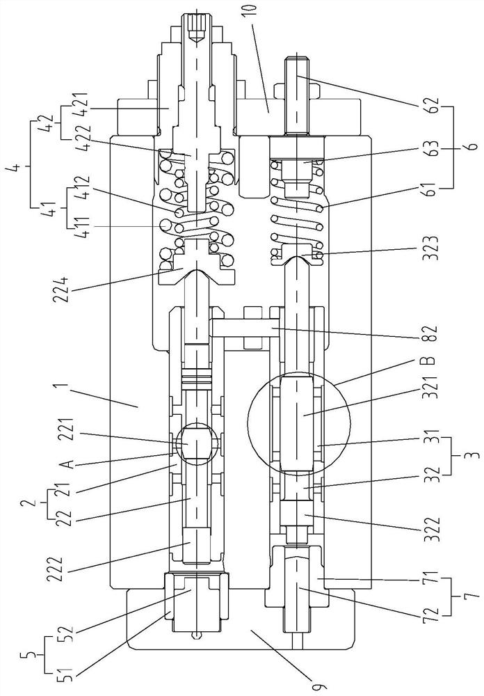
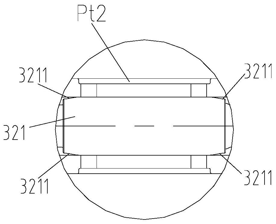
[0046] like Figure 1-11 As shown, this embodiment provides a variable variable servo valve, which includes a valve body 1, and a power valve 2 and a displacement valve 3 are arranged side by side in the valve body 1. Specifically, two installation holes are opened in parallel in the valve body 1. The power valve 2 and the displacement valve 3 are respectively arranged in two installation holes. The power valve 2 and the displacement valve 3 can realize the power control and displacement control of the variable displacement pump by controlling the movement of the servo piston. The power valve 2 and the displacement valve 3 can be controlled separately or cooperatively.

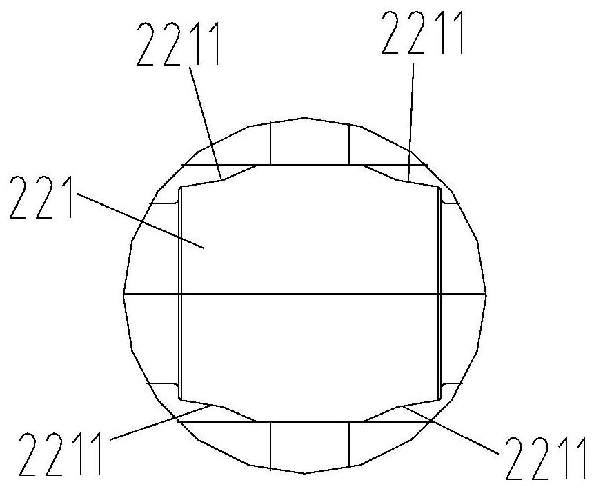
[0047] The power valve 2 includes a power valve sleeve 21 and a power valve core 22 , the power valve sleeve 21 is axially slidably disposed in the valve body 1 , and the power valve core 22 is axially slidably disposed in the power valve sleeve 21 . The power valve sleeve 21 is opened with the pressure oil ...

Embodiment 2

[0062] like Figure 12 As shown, this embodiment is basically the same as Embodiment 1, the only difference is that there are two pressure oil ports Po1 of the power valve sleeve, and the pressure oil ports Po1 of the two power valve sleeves are used to connect pressure oil, and the power valve core 21 is also provided with a third core 223, the third core 223 is located on the side of the second core 222 away from the first core 221, the outer diameter of the third core 223 is D3, D1>D2>D3, An area difference S1 is formed between D1 and D2, and an area difference S2 is formed between D2 and D3, forming two pressure steps. The pressure oil ports Po1 of the two power valve sleeves are respectively located between the first core 221 and the second core 222 and between the second core 222 and the third core 223 . The force direction of the pressure oil entering through the pressure oil port Po1 of the two power valve sleeves on the power spool 22 is opposite to the force directi...


PUM


Abstract

The invention relates to a variable servo valve, a power servo valve and a variable pump. The variable servo valve comprises a valve body. A power valve and a displacement valve are arranged in the valve body side by side. The power valve comprises a power valve sleeve and a power valve element. The power valve sleeve is arranged in the valve body in the manner of being capable of sliding axially.The power valve element is arranged in the power valve sleeve in the manner of being capable of sliding axially. The power valve comprises a displacement valve sleeve and a displacement valve element. The displacement valve sleeve is arranged in the valve body in the manner of being capable of sliding axially. The displacement valve element is arranged in the displacement valve sleeve in the manner of sliding axially. A feedback rod drives the power valve sleeve and the displacement valve sleeve to move so as to recover balance under the action of feedback force. A control oil port on the power valve sleeve and a control oil port on the displacement valve sleeve communicate with each other. A servo piston large chamber oil port of the power valve sleeve is controlled by the power valve element to communicate with a pressure oil port of the power valve sleeve or communicate with the control oil port of the power valve sleeve. According to the variable servo valve, the power servo valveand the variable pump, the problems that in the prior art, a displacement control device is complex in structure, large in number of parts, difficult to process or disassemble, and high in cost are solved.

Description

technical field [0001] The invention relates to the field of hydraulic controllers, in particular to a variable variable servo valve, a power servo valve and a variable variable pump. Background technique [0002] In hydraulic excavators, loaders, cranes, bulldozers, cement pump trucks and other machinery used in construction machinery, hydraulic actuators such as oil cylinders are used to drive mechanical movement. On the other hand, various actuators are used, and oil pressure is used for the driving of these actuators. On different machines and under different working conditions, the movement forms of actuators are diversified and randomized, which requires the power unit hydraulic pump used in construction machinery to output different flow rates according to different working conditions to meet the needs of mechanical operations. . [0003] For example, the Japanese patent No. JP6276664B2 discloses a flow control device for a variable displacement hydraulic pump, whic...

Claims


Application Information

Patent Timeline
Patent Type & Authority Patents(China)
IPC IPC(8): F04B49/22F04B1/295F04B1/324
CPCF04B1/295F04B1/324F04B49/22
Inventor 汪立平刘艳艳董可赵文俊
Owner JIANGSU HENGLI HYDRAULIC TECH CO LTD
Why Eureka
Try Eureka