Test fixture for LED display circuit board

A technology for testing jigs and circuit boards, which is used in electronic circuit testing, measuring electricity, measuring devices, etc., and can solve problems such as inability to contact probes and pads, uneven force on the circuit board, and bending and deformation of the circuit board. Improve test efficiency, good sealing and uniform force

Pending Publication Date: 2019-10-08
AET DISPLAY LTD +1
View PDF0 Cites 0 Cited by
  • Summary
  • Abstract
  • Description
  • Claims
  • Application Information

AI Technical Summary

Problems solved by technology

However, due to the elasticity of the circuit board, many probes will cause uneven force on the circuit board after contacting the pads, and the circuit board will be bent and deformed, resulting in the inability to contact some probes and pads, which will affect the test.

Method used


Image

  • Test fixture for LED display circuit board
  • Test fixture for LED display circuit board

Examples


Embodiment Construction

[0026] In order to make the object, technical solution and advantages of the present invention clearer, the present invention will be further described in detail below in conjunction with the accompanying drawings.

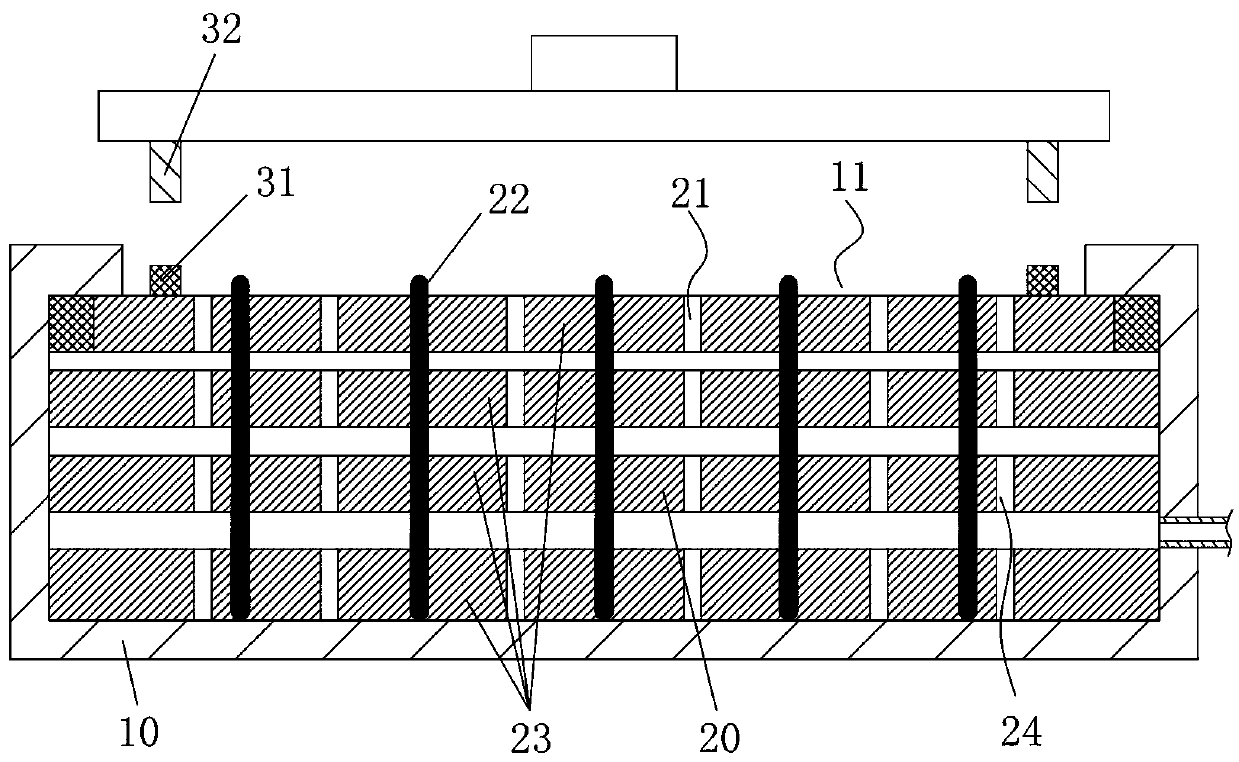
[0027] Such as figure 1 As shown, the embodiment provided by the present invention is a test fixture for an LED display circuit board, which includes a negative pressure cavity 10 and a lower mold 20; the negative pressure cavity 10 is provided with an upper opening 11, and the lower mold 20 is installed on the negative pressure cavity. In the pressure chamber 10 and seal the upper opening 11; the top surface of the lower mold 20 is provided with an air suction hole 21, one end of the air suction hole 21 communicates with the upper opening 11, and the other end communicates with the interior of the negative pressure chamber 10, and the lower mold 20 is provided with There is a probe 22 protruding from the top surface of the lower die 20 .

[0028] The lower mold ...


PUM


Abstract

The invention discloses a test fixture for an LED display circuit board. The test fixture comprises a negative pressure chamber and a lower mold. An upper opening is formed in the negative pressure chamber; and the lower mold is installed in the negative pressure chamber and the upper opening is sealed. An air suction hole is formed in the top surface of the lower mold; on end of the air suction hole is communicated with the upper opening and the other end is communicated with the inside of the negative pressure chamber. A probe protruding from the top surface of the lower mold is arranged inthe lower mold. According to the invention, when an LED display circuit board is placed on the top surface of the lower mold, the air suction hole exhaust air to generate the negative pressure betweenthe circuit board and the lower mold, so that the LED display circuit board is pressed against the top surface of the lower mold under the action of atmospheric pressure. Therefore, the compaction ofthe LED display circuit board can be realized without the downward pressing of the upper mold. Under the effect of the atmospheric pressure, the LED display circuit board bears forces uniformly and does not make bending and deformation; and the probe of the lower mold and the bonding pad of the LED display circuit board are in full contact, so that testing is performed normally.

Description

technical field [0001] The invention relates to the technical field of testing electronic components, in particular to a test fixture for an LED display circuit board. Background technique [0002] Circuit boards need to be tested during production. A traditional test fixture includes an upper mold and a lower mold, and a plurality of probes are arranged on the top surface of the lower mold. During the test, the circuit board is placed on the top of the lower mold, the upper mold presses the top surface of the circuit board downward, and the probes are in contact with and electrically connected to the pads on the bottom surface of the circuit board. [0003] The LED display circuit board includes an IC surface and a lamp surface arranged up and down. Various uneven electronic components are mounted on the IC surface, and the upper mold in the traditional test fixture cannot compress the IC surface. The lamp surface is provided with densely distributed welding pads for LED...

Claims


Application Information

Patent Timeline
IPC IPC(8): G01R31/28
CPCG01R31/2887
Inventor 梁文骥孙明许晋彰赵春雷
Owner AET DISPLAY LTD
Why Eureka
Try Eureka