Radar optical device guiding error compensation method

A radar optics and error compensation technology, applied in the field of guidance error compensation, can solve the problems of inability to accurately guide radar optical equipment, limited sensor accuracy, and low efficiency.

Inactive Publication Date: 2019-10-08
BEIJING INST OF REMOTE SENSING EQUIP
View PDF6 Cites 4 Cited by
  • Summary
  • Abstract
  • Description
  • Claims
  • Application Information

AI Technical Summary

Problems solved by technology

[0007] The purpose of the present invention is to provide a method for compensating the guidance error of radar optical equipment to solve the problem found in the test process that when a simple device such as a geomagnetic sensor is used to orient the radar optical equipment, the accuracy of the sensor is limited and it is easily affected by the surrounding magnetic field and metal objects. , so that there is still a slight deviation between the oriented table coordinate system and the local geographic coordinate system, resulting in inaccurate guidance information such as pitch angle and azimuth angle calculated based on GPS information, and the radar optical equipment cannot be accurately guided, which affects the data. Acquisition quality, manual fine-tuning of the turntable based on experience, time-consuming and inefficient problems

Method used


Image

  • Radar optical device guiding error compensation method
  • Radar optical device guiding error compensation method
  • Radar optical device guiding error compensation method

Examples


Embodiment Construction

[0065] The present invention will be described in further detail below in conjunction with accompanying drawing and specific embodiment, according to following description and claims, the advantages and characteristics of the present invention will be clearer; The precise proportions are only used for the purpose of conveniently and clearly assisting in describing the embodiments of the present invention.

[0066] Although the present invention can be expanded in various forms of modification and replacement, some specific implementation figures are also listed and explained in detail in the description; it should be understood that the inventor's starting point is not to limit the invention to the specific implementation illustrated. For example, on the contrary, the inventor's starting point is to protect all improvements, equivalent substitutions and modifications given within the spirit or scope defined by this claim.

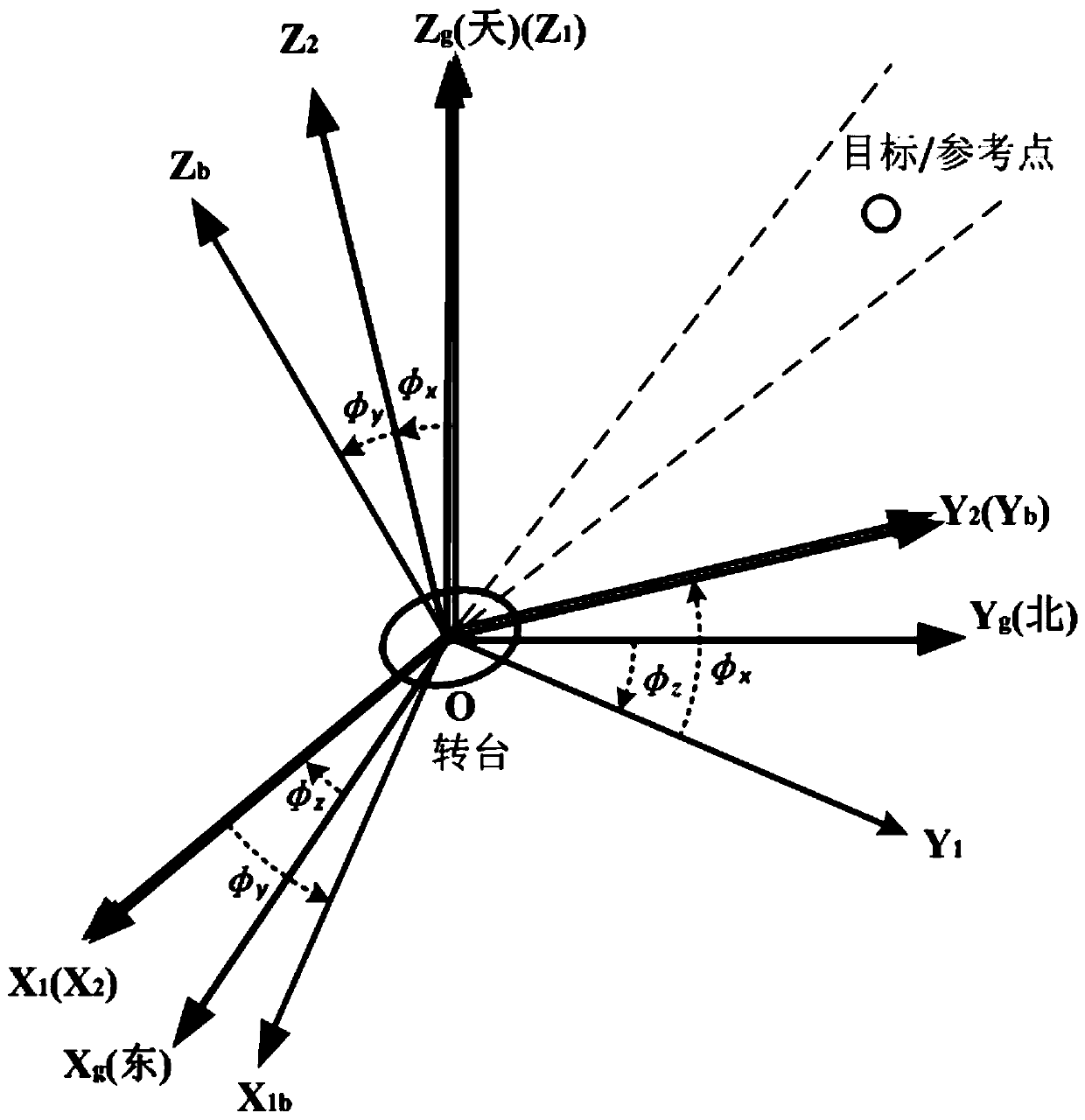
[0067] figure 1 It is a schematic diagram of transfo...


PUM


Abstract

The invention discloses a radar optical device guiding error compensation method. The implementation process is that a radar optical device is fixed on a turntable and the turntable is leveled to adjust the azimuth to a selected reference direction; one to two reference surface features are selected, a servo motion mechanism is controlled to align the foresight direction of the radar optical device with a reference point position, and a reference point surface feature is enabled to be located at the field of view center of the device; the position of the turntable, the longitude, latitude andheight of the reference point position, and the pitching azimuth angle of the servo mechanism are recorded to determine errors of the device relative to a geographic coordinate system; and error compensation is carried out on obtained guiding information. The method is used for the outfield test of radar optical device data acquisition; and compensation is carried out on the GPS guiding information through measuring error angles between turntable board coordinate systems and local geographic coordinate systems, so that accurate guiding for the radar optical devices is realized and the qualityof the acquired data is ensured.

Description

technical field [0001] The invention relates to a guidance error compensation method, in particular to a guidance error compensation method for radar optical equipment. Background technique [0002] When studying anti-jamming and target tracking problems of radar optical equipment, it is necessary to collect data of stationary or moving targets in the field test environment. [0003] In order to obtain target data under different interference backgrounds, radar optical equipment needs to use external target guidance information to achieve precise tracking of targets. [0004] In the field test environment, after the radar optical equipment is installed on the turntable, the orientation sensor is generally used for orientation operation, so that the table coordinate system on the turntable coincides with the local geographic coordinate system (northeast sky coordinate system) as much as possible. [0005] During the test, it was found that when the radar optical equipment is...

Claims


Application Information

Patent Timeline
IPC IPC(8): G01S7/497
CPCG01S7/497
Inventor 蔺震张晓峰金威
Owner BEIJING INST OF REMOTE SENSING EQUIP
Why Eureka
Try Eureka