Ultra-wide bandwidth beam low profile back cavity antenna structure

An antenna structure, wide beam technology, applied in the microwave field, can solve problems such as damage, manual cleaning inconvenience, impact force, etc., and achieve the effect of saving resources

Active Publication Date: 2019-10-08
江苏维航精仪科技有限公司
View PDF6 Cites 13 Cited by
  • Summary
  • Abstract
  • Description
  • Claims
  • Application Information

AI Technical Summary

Problems solved by technology

[0005] This kind of antenna structure is usually fixed and installed in high open places. On the one hand, the surface of the shell is easy to adhere to fine impurities such as dust, which makes manual cleaning very inconvenient. It is easy to cause impact and damage due to strong wind when using

Method used


Image

  • Ultra-wide bandwidth beam low profile back cavity antenna structure
  • Ultra-wide bandwidth beam low profile back cavity antenna structure
  • Ultra-wide bandwidth beam low profile back cavity antenna structure

Examples


Embodiment Construction

[0023] The following will clearly and completely describe the technical solutions in the embodiments of the present invention with reference to the accompanying drawings in the embodiments of the present invention. Obviously, the described embodiments are only some, not all, embodiments of the present invention.

[0024] In describing the present invention, it should be understood that the terms "upper", "lower", "front", "rear", "left", "right", "top", "bottom", "inner", " The orientation or positional relationship indicated by "outside", etc. is based on the orientation or positional relationship shown in the drawings, and is only for the convenience of describing the present invention and simplifying the description, rather than indicating or implying that the referred device or element must have a specific orientation, so as to Specific orientation configurations and operations, therefore, are not to be construed as limitations on the invention.

[0025] refer to Figure ...


PUM


Abstract

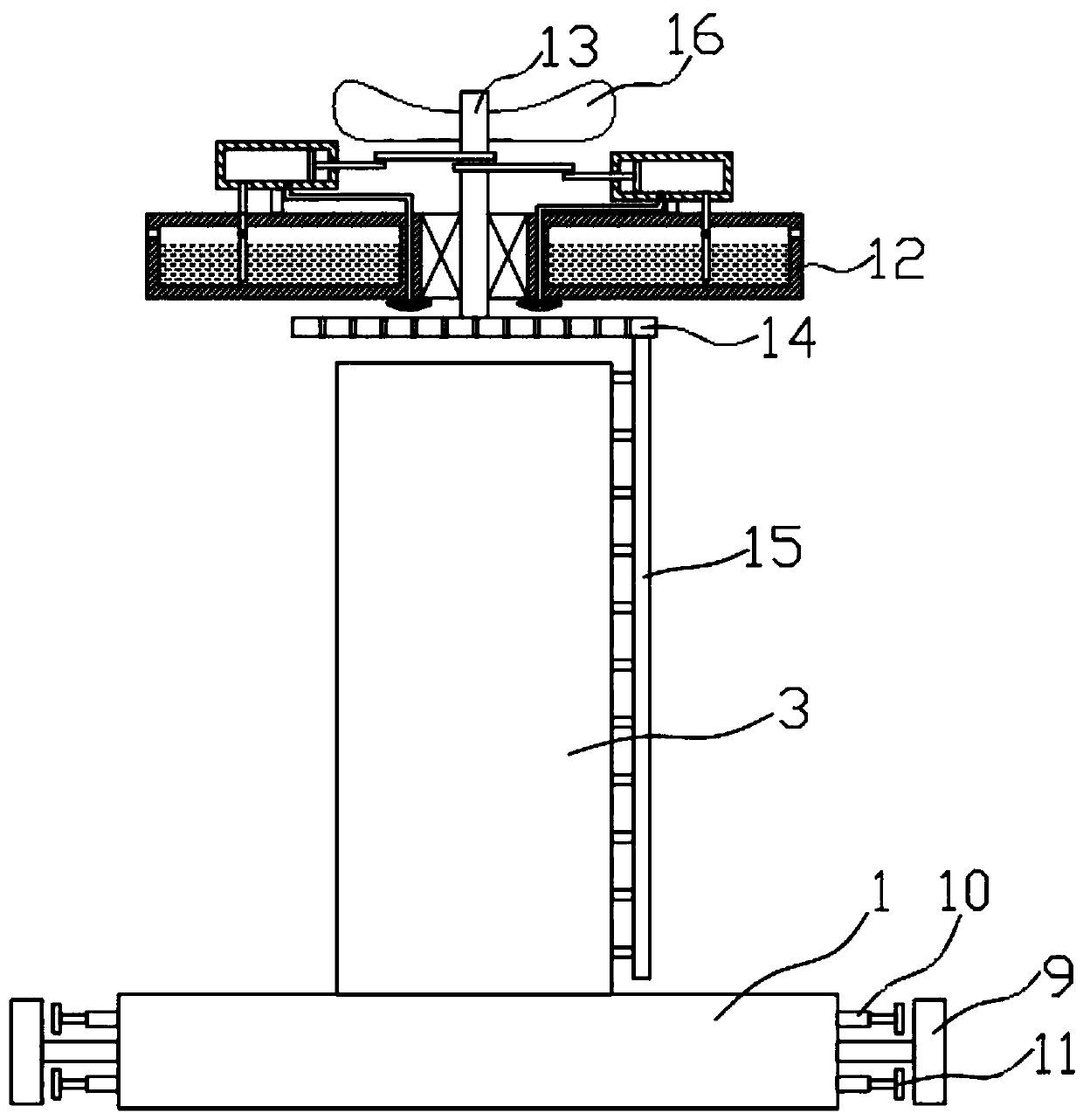
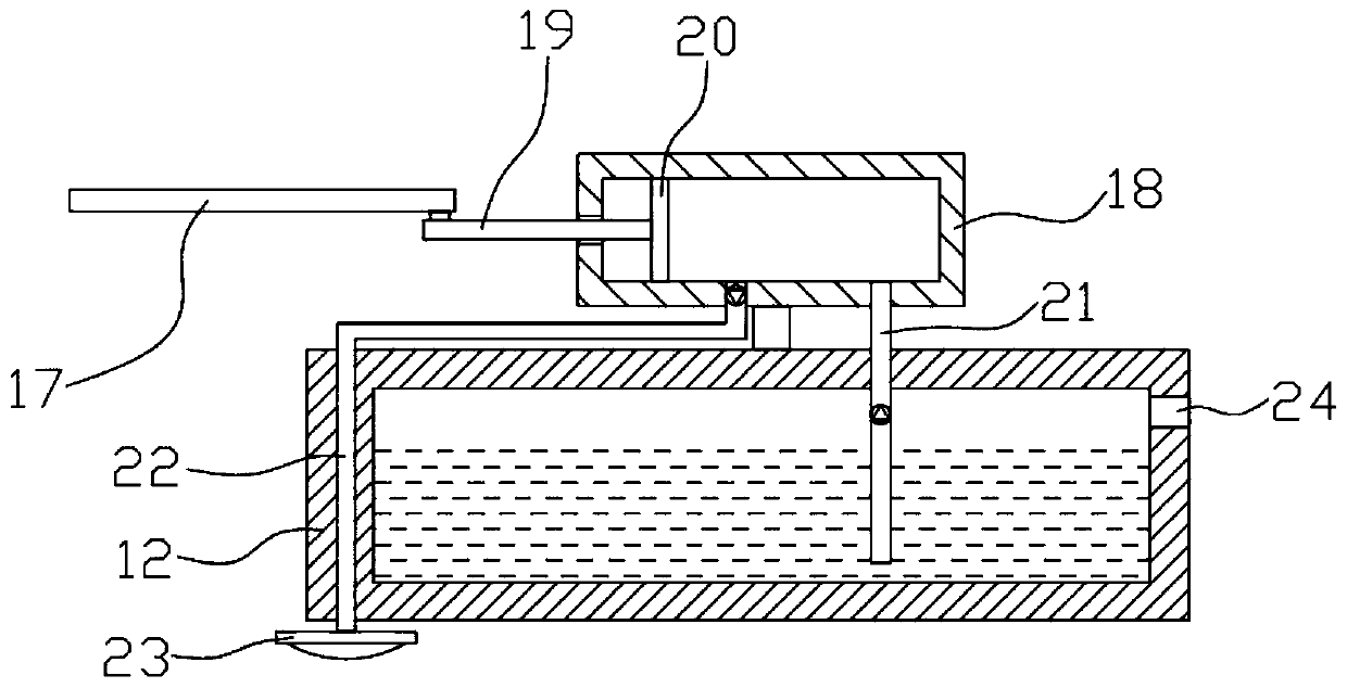
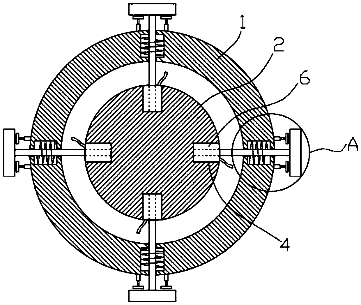
The invention discloses an ultra-wide bandwidth beam low profile back cavity antenna structure which comprises a mounting ring plate. An antenna base is arranged in the mounting ring plate. A cylindrical antenna casing is fixedly connected with the upper end of the antenna base. The mounting ring plate has a plurality of shock absorbing mounting units distributed circumferentially equiangularly around the antenna casing. The upper end of the antenna casing is provided with a pneumatic self-cleaning unit. Each shock absorbing mounting unit comprises a circular slot arranged on the antenna baseand a cavity formed in the mounting ring plate, and the slot corresponds to the cavity in position. An inserted rod is inserted in each slot. The outer wall of one end, which is located in the slot, of each inserted rod is fixedly connected with an expansion airbag. According to the invention, the pneumatic self-cleaning unit can automatically clean the antenna casing by using the wind power, which prevents manual cleaning and reduces energy consumption; and the shock absorbing mounting units are arranged, which can be used for shock absorption when the wind is large, so as to avoid damage.

Description

technical field [0001] The invention relates to the field of microwave technology, in particular to a cavity-backed antenna structure with an ultra-wide bandwidth beam and low profile. Background technique [0002] As a key component, a high-performance antenna can not only significantly improve the performance of the radar system and obtain a good reception effect, but also greatly relieve the index pressure of the subsequent radio frequency circuit and reduce the cost of the radar system. In radar applications, the requirements for antennas are not only excellent radiation performance, but also requirements for coverage area, volume and weight. [0003] At present, in order to realize the antenna structure of the ultra-wide bandwidth beam, the Vivaldi antenna form of the pure metal structure is mostly used. This antenna form has certain bandwidth advantages, but it is relatively heavy and it is difficult to achieve low-profile performance. However, although the antenna i...

Claims


Application Information

Patent Timeline
Patent Type & Authority Applications(China)
IPC IPC(8): H01Q1/00H01Q1/12B08B3/02B08B1/04
CPCB08B1/04B08B3/02H01Q1/00H01Q1/005H01Q1/1207
Inventor 梁朴朴
Owner 江苏维航精仪科技有限公司
Why Eureka
Try Eureka