Moisture-proof dry cabinet
A dry type, cabinet technology, applied in the direction of casing/cabinet/drawer parts, electrical equipment casing/cabinet/drawer, electrical components, etc., can solve the problems of corrosion damage of internal components, poor heat dissipation of the cabinet, etc. Achieve the effect of adjusting, realizing the drying range, and improving the moisture-proof effect
- Summary
- Abstract
- Description
- Claims
- Application Information
AI Technical Summary
Problems solved by technology
Method used
Image
Examples
Embodiment 1
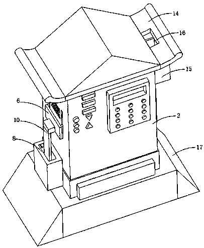
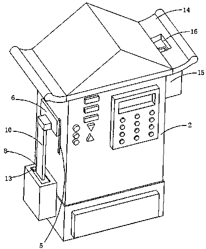
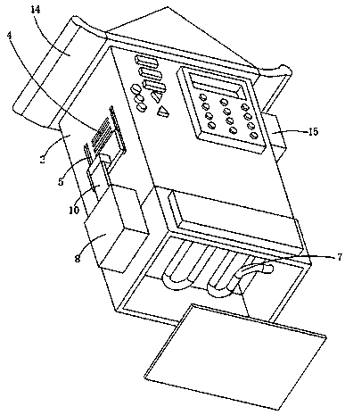
[0032] refer to Figure 1-4 , a moisture-proof dry cabinet, including an inner cabinet 1 and an outer cabinet 2, the inner cabinet 1 is connected to the top inner wall of the outer cabinet 2, and a hygroscopic net plate 3 is connected between the inner cabinet 1 and the outer cabinet 2, The outer side wall of the outer cabinet body 2 is excavated with a vent 4, and the outer side wall of the outer cabinet body 2 is also dug with a vertically arranged chute 5, the chute 5 is arranged on the outside of the vent 4, and a U type baffle plate 6, the top of the outer cabinet body 2 is connected with a rain collection assembly, the water outlet end of the rain collection assembly is connected with a communication pipe 7, and the end of the communication pipe 7 away from the water collection assembly is placed in the inner cavity of the outer cabinet body 2, and is connected with the inner The bottom inner wall of the cabinet body 1 is offset, and one end of the connecting pipe 7 pass...
Embodiment 2
[0040] refer to figure 1 and Figure 5 , a moisture-proof dry cabinet, basically the same as Embodiment 1, furthermore, the bottom inner wall of the outer cabinet body 2 is also connected with a lifting platform 17;
[0041] The lifting platform 17 is mainly composed of a base 171 and a hydraulic drive assembly. The hydraulic drive assembly is connected to the bottom inner wall of the base 171. The outer cabinet body 2 is slidably connected in the base 171. The driving end of the hydraulic drive assembly is connected to the outer cabinet body 2. The outer wall of the bottom is connected;
[0042] The hydraulic drive assembly is mainly composed of a hydraulic pump 172 and a hydraulic cylinder 173. The hydraulic cylinder 173 is connected to the driving end of the hydraulic pump 172. The hydraulic pump 172 is connected to the bottom inner wall of the base 171. The end of the hydraulic cylinder 173 away from the hydraulic pump 172 is connected to the outer cabinet. the bottom of...
Embodiment 3
[0045] refer to Figure 4 , a moisture-proof drying cabinet, basically the same as Embodiment 1, furthermore, the inner side wall of the inner cabinet body 1 is dug with a slot, and a drying box 18 is slidingly connected in the slot, and the drying box 18 is filled with a desiccant , the top of the drying box 18 is connected with a stay rope 19, and the end of the stay rope 19 away from the drying box 18 extends outward through the inner cabinet body 1 and the outer cabinet body 2, and the extension end is connected with the connecting rod 10, and the bottom of the outer cabinet body 2 Both the inner wall and the moisture-absorbing net plate 3 are connected with a fixed pulley 20, and the stay rope 19 located in the cavity of the outer cabinet body 2 bypasses the fixed pulley 20;
[0046] As the floating plate 9 rises, the connecting rod 10 is driven to pull the drying box 18 to realize the adjustment function of the position of the drying box 18 and further realize the adjust...
PUM
| Property | Measurement | Unit |
|---|---|---|
| Diameter | aaaaa | aaaaa |
Abstract
Description
Claims
Application Information
 - R&D
- Intellectual Property
- Life Sciences
- Materials
- Tech Scout
- Unparalleled Data Quality
- Higher Quality Content
- 60% Fewer Hallucinations
Browse by: Latest US Patents, China's latest patents, Technical Efficacy Thesaurus, Application Domain, Technology Topic, Popular Technical Reports.
© 2025 PatSnap. All rights reserved.Legal|Privacy policy|Modern Slavery Act Transparency Statement|Sitemap|About US| Contact US: help@patsnap.com


