Positioning jig

A technology for positioning fixtures and positioning plates, which is applied in the direction of manufacturing tools, workpiece clamping devices, etc., can solve problems such as waste, unusable fixtures, and material waste, and achieve the effect of improving versatility

Inactive Publication Date: 2019-10-11
GUANGDONG EVERWIN PRECISION TECH
View PDF5 Cites 3 Cited by
  • Summary
  • Abstract
  • Description
  • Claims
  • Application Information

AI Technical Summary

Problems solved by technology

[0003] At present, most of the jigs in the industry are integrated, that is, the positioning parts, supporting parts and the bottom plate are designed as one. When processing the jig, the whole piece of raw material is usually cut off by cutting and other processes, similar to engraving, and retained. The part that needs to be used, remove the part due to interference or no value, resulting in serious waste of materials
[0004] The current fixtures are not very flexible in product positioning. Changes in product structure design may cause the original fixtures to not be used normally. Therefore, the original fixtures are scrapped or need to be reworked. At the same time, the original fixtures can only be used for one type. Products, when the product or project is over, the fixture will be scrapped, causing great waste

Method used


Image

  • Positioning jig
  • Positioning jig
  • Positioning jig

Examples


Embodiment Construction

[0040] In order to facilitate the understanding of the present invention, the present invention will be described more fully below with reference to the relevant drawings. Preferred embodiments of the invention are shown in the accompanying drawings. However, the present invention can be embodied in many different forms and is not limited to the embodiments described herein. Rather, these embodiments are provided so that the understanding of the present disclosure will be better and more complete.

[0041] It should be noted that when an element is referred to as being “fixed” to another element, it can be directly on the other element or there can also be an intervening element. When an element is referred to as being "connected to" another element, it can be directly connected to the other element or intervening elements may also be present. In contrast, when an element is referred to as being "directly on" another element, there are no intervening elements present. The t...


PUM


Abstract

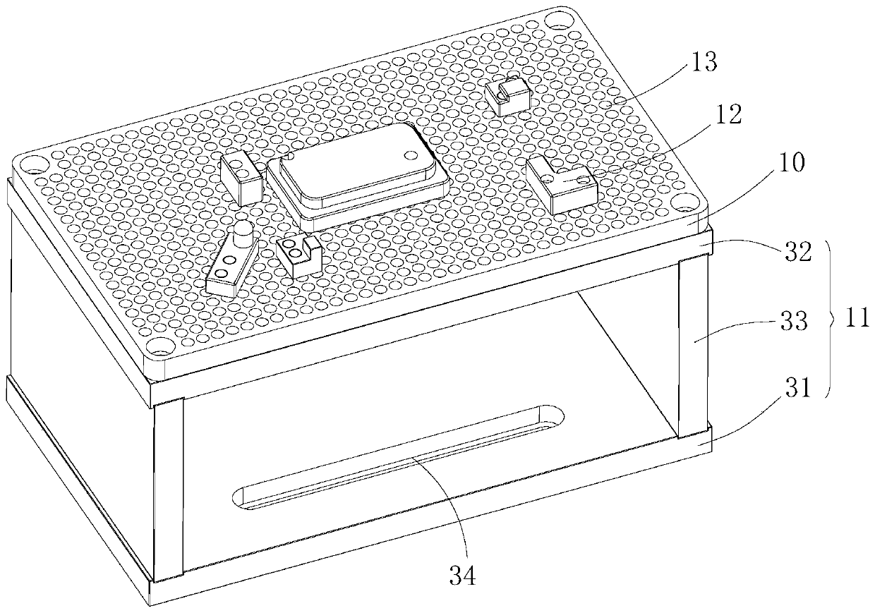
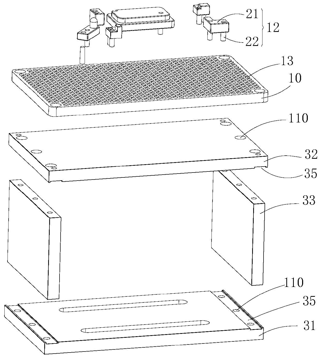
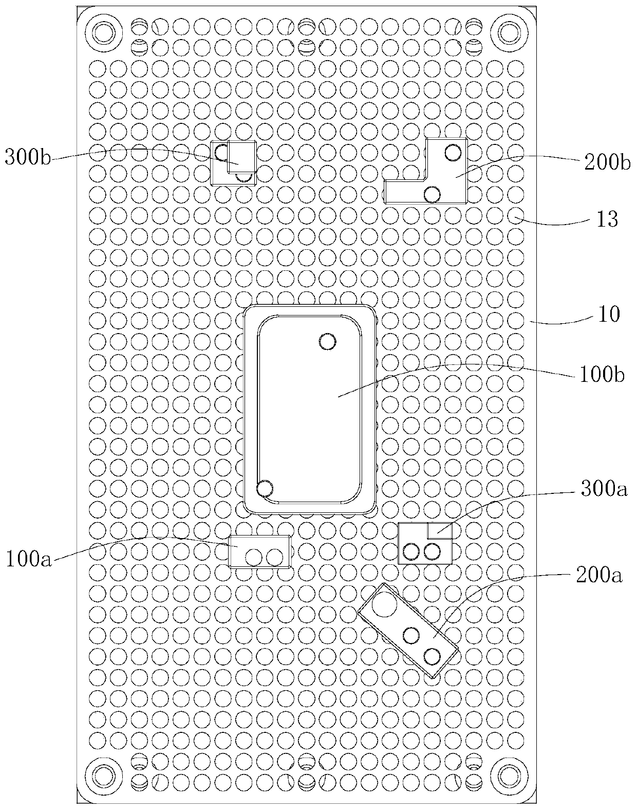
The invention relates to a positioning jig. The positioning jig comprises a base assembly, a positioning plate and an insert assembly, wherein the positioning plate is arranged on the base assembly, and a plurality of inserting holes distributed in an array mode are formed in the positioning plate; the insert assembly is detachably connected to the positioning plate, the insert assembly comprisesan insert body and at least two bolts arranged on the insert body, wherein the insert body is inserted and matched with inserting holes through the bolts, and one bolt is inserted into one inserting hole correspondingly; and the insert assembly can be matched with the inserting holes in different positions on the positioning plate through the bolts, so that the insert assembly can be installed atdifferent positions of the positioning plate. A jig does not need to be independently designed for different workpieces, so that the universality of the jig is improved.

Description

technical field [0001] The invention relates to the technical field of mechanical processing, in particular to a positioning jig. Background technique [0002] Fixtures are often used in industrial production as a tool to assist in controlling position or movement, so as to facilitate pre-positioning of workpieces that need to be positioned for production. [0003] At present, most of the jigs in the industry are integrated, that is, the positioning parts, supporting parts and the bottom plate are designed as one. When processing the jig, the whole piece of raw material is usually cut off by cutting and other processes, similar to engraving, and retained. For the parts that need to be used, remove the parts that are interfering or worthless, resulting in a serious waste of materials. [0004] The current fixtures are not very flexible in product positioning. Changes in product structure design may cause the original fixtures to not be used normally. Therefore, the original ...

Claims


Application Information

Patent Timeline
IPC IPC(8): B25B11/00
CPCB25B11/00
Inventor 周荣虎任项生
Owner GUANGDONG EVERWIN PRECISION TECH
Why Eureka
Try Eureka