Control method and system of electric vehicle electric pile of fuel cell
A fuel cell and control method technology, which is applied in battery/fuel cell control devices, fuel cells, electric vehicles, etc., can solve the problems of burning out the stack, high risk, and low safety performance of the stack, so as to improve safety performance, The effect of avoiding deterioration of failure
Active Publication Date: 2019-10-11
WEICHAI POWER CO LTD
6 Cites 9 Cited by
AI-Extracted Technical Summary
Problems solved by technology
[0003] However, the existing fuel cell electric vehicles do not have the protection function of stack insulation failure, which will lead to deterioration of stack insulation failure ...
View moreMethod used
Based on this, the application provides a control method and system for a fuel cell electric vehicle stack, the control method includes: obtaining the insulation resistance of the stack, wherein the stack includes: at least two sub-stacks connected in parallel ; When it is judged that the insulation resistance of the electric stack is less than the first preset threshold value, after disconnecting the sub-stack whose insulation failure is connected to the DC bus, the electric stack enters the fault operation mode. It can be seen from the above that, in the technical solution provided by this application, by judging that the insulation resistance of the stack is less than the first preset threshold, it is determined that the stack has an insulation failure fault, and then the sub-stacks that have an insulation failure fault are checked. Locate and disconnect the sub-stack with insulation failure from the DC bus, and then make the stack run in a faulty operation mode to protect the stack and prevent the insulation failure of the stack from worsening and burning the stack , improve the safety performance of the stack.
It should be noted that the electric stack generates electricity by introducing air, gas and water, and the electricity sent is provided to the vehicle load for use. When it is judged that the insulation resistance of the electric stack is less than the first preset threshold, it means At this time, the electric stack has an insulation failure fault. At this time, the electric stack is controlled to stop introducing air, gas and water, and the connection between the electric stack and the load of the vehicle is disconnected, and the electric stack stops discharging and stops working to avoid electric stack discharge. Attenuate the performance of the stack or cause a short circuit of the stack to protect the stack.
It should be noted that: if there is no...
View moreAbstract
The invention provides a control method and system of an electric vehicle electric pile of a fuel cell. The control method comprises the following steps that 1, an insulation resistance of the electric pile is obtained, wherein the electric pile comprises at least two sub-electric piles which are connected in parallel; 2, when it is judged that the insulation resistance of the electric pile is smaller than a first preset threshold value, the electric pile enters a fault operation mode after disconnecting the connection between the sub-electric piles of the insulation failure and a direct-current bus. According to the technical scheme, when the insulation resistance of the electric pile is smaller than the first preset threshold value by judgment, an insulation failure fault occurring in the electric pile is determined, and the sub-electric piles are positioned which has an insulation failure fault, the connection between the insulation failure sub-electric piles and the direct-currentbus is disconnected, and the electric pile is enabled to operate in a fault operation mode, so that the fault of the electric pile can be prevented from deteriorating, the electric pile can be burnt out, and the safety performance of the electric pile can be improved.
Application Domain
Technology Topic
Image
Examples
- Experimental program(1)
Example Embodiment
[0058] The following will clearly and completely describe the technical solutions in the embodiments of the present invention with reference to the accompanying drawings in the embodiments of the present invention. Obviously, the described embodiments are only some, not all, embodiments of the present invention. Based on the embodiments of the present invention, all other embodiments obtained by persons of ordinary skill in the art without making creative efforts belong to the protection scope of the present invention.
[0059] As mentioned in the background technology, the fuel cell electric vehicles in the prior art do not have the protection function of the stack insulation failure, which will lead to the deterioration of the stack insulation failure and burn out the stack. The safety performance is low and the risk is high.
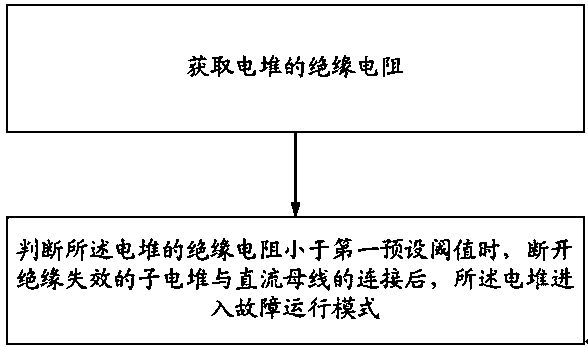
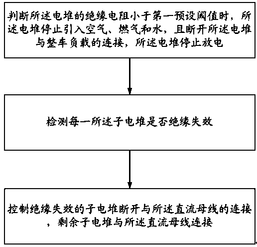
[0060] Based on this, the present application provides a control method and system for a fuel cell electric vehicle stack. The control method includes: obtaining the insulation resistance of the stack, wherein the stack includes: at least two sub-stacks connected in parallel; When the insulation resistance of the electric stack is less than the first preset threshold, the electric stack enters the failure operation mode after disconnecting the sub-stack whose insulation failure is connected to the DC bus. It can be seen from the above that, in the technical solution provided by this application, by judging that the insulation resistance of the stack is less than the first preset threshold, it is determined that the stack has an insulation failure fault, and then the sub-stacks that have an insulation failure fault are checked. Locate and disconnect the sub-stack with insulation failure from the DC bus, and then make the stack run in a faulty operation mode to protect the stack and prevent the insulation failure of the stack from worsening and burning the stack , improve the safety performance of the stack.
[0061] In order to achieve the above purpose, the technical solutions provided by the embodiments of the present application are as follows, specifically combined with Figure 1 to Figure 4 The technical solutions provided by the embodiments of the present application are described in detail.
[0062] refer to figure 1 as shown, figure 1 A flow chart of a control method for a fuel cell electric vehicle stack provided in an embodiment of the present application;
[0063] A control method for a fuel cell electric vehicle stack, comprising:
[0064] Obtaining the insulation resistance of the electric stack, wherein the electric stack includes: at least two sub-stacks connected in parallel;
[0065] When it is judged that the insulation resistance of the electric stack is less than a first preset threshold, the electric stack enters a failure operation mode after disconnecting the sub-stack whose insulation failure is connected to the DC bus.
[0066] It should be noted that: see Figure 4 As shown, the electric stack is composed of at least two sub-stacks connected in parallel, the positive pole of each sub-stack is connected to the positive pole of the DC bus, and the negative pole of each sub-stack is connected to the negative pole of the DC bus.
[0067] When the electric stack has an insulation failure fault, its resistance will inevitably be abnormal and not within the normal range, so the first preset threshold in the embodiment of the present application is used to judge whether the electric stack has an insulation failure fault. The embodiment of the application does not limit the specific value of the "first preset threshold", which needs to be selected according to specific calculations based on actual applications.
[0068] In this embodiment, when the insulation resistance of the electric stack is less than the first preset threshold value, it means that the electric stack has an insulation failure fault, and the electric stack is composed of at least two sub-stacks connected in parallel, therefore, there must be The insulation failure of the sub-stack will cause the insulation failure of the sub-stack. Therefore, after the insulation failure of the sub-stack is judged, it is necessary to locate the sub-stack with the insulation failure and connect the sub-stack with the failure. The connection of the DC bus is disconnected, that is, the sub-stacks with insulation failures are stopped from working, and then the sub-stacks are put into a fault operation mode to protect the sub-stacks with insulation failures.
[0069] Each sub-stack is composed of a series of battery slices in series, including air intake and exhaust ports; gas intake and exhaust ports, and power positive and negative output ports. The cathode of the sub-stack is fed with air, and the anode is fed with gas. At a certain temperature, an electrochemical reaction occurs through the battery sheet. The cathode oxygen becomes a positive ion, which is transferred to the anode through the electrolyte, and reacts with the hydrogen ions and CO of the anode to generate water and CO2, electrons pass through the load at the positive and negative poles of the sub-stack to form an electrical circuit.
[0070] The electric stack of the fuel cell may also include: sub-stacks, reformers, heat exchangers, burners, steam generators and other components, which generate the required electric power through electrochemical reactions, that is, the electric stacks And water work to generate power for the power battery and high-voltage components.
[0071] like figure 2 As shown, in an embodiment of the present application, when it is judged that the insulation resistance of the electric stack is less than the first preset threshold value, disconnecting the sub-stack whose insulation failure is connected to the DC bus includes:
[0072] When it is judged that the insulation resistance of the electric stack is less than the first preset threshold, the electric stack stops introducing air, gas and water, and disconnects the electric stack from the vehicle load, and the electric stack stops discharging;
[0073] Detecting whether each of the sub-stacks has an insulation failure;
[0074] The sub-stacks that control insulation failure are disconnected from the DC bus, and the remaining sub-stacks are connected to the DC bus.
[0075] It should be noted that the electric stack generates electricity by introducing air, gas and water, and provides the generated electricity to the vehicle load. When it is judged that the insulation resistance of the electric stack is less than the first preset threshold, it means that the electric stack Insulation failure of the stack occurs. At this time, the stack is controlled to stop introducing air, gas and water, and the connection between the stack and the load of the vehicle is disconnected. The performance of the battery will attenuate or cause the stack to be short-circuited to protect the stack.
[0076] Then detect each of the sub-stacks, find the sub-stacks with insulation failure, control the sub-stacks with insulation failure to disconnect from the DC bus, and control the remaining sub-stacks to connect to the DC bus to form a running the stack.
[0077] In an embodiment of the present application, detecting whether each sub-stack has insulation failure includes:
[0078] Obtaining the first insulation resistance of the electric stack when all the sub-stacks are connected to the DC bus;
[0079] Disconnecting the connection between one of the sub-stacks and the DC bus, and obtaining the second insulation resistance of the corresponding stack formed by the sub-stacks connected to the DC bus;
[0080] judging whether the disconnected sub-stacks have insulation failure by using the first insulation resistance and the second insulation resistance;
[0081] Disconnecting the connection between one of the sub-stacks and the DC bus again, and obtaining the third insulation resistance of the corresponding stack formed by the sub-stacks connected to the DC bus;
[0082] judging by the second insulation resistance and the third insulation resistance whether the sub-stacks disconnected again have insulation failure;
[0083] Repeat the above steps until it is judged whether all sub-stacks have insulation failure.
[0084] It should be noted that the insulation resistance is essentially the resistance of the stack, that is, the parallel resistance of all sub-stacks connected to the DC bus, wherein the first insulation resistance is that all sub-stacks are connected to the DC bus The parallel resistance of the second insulation resistance is the parallel connection resistance of the remaining sub-stacks after disconnecting any one of the sub-stacks from the DC bus, so that it can be determined by the first insulation resistance and the second insulation resistance Disconnect the resistance of the sub-stack connected to the DC bus, compare the resistance with a second preset threshold, and if the resistance is smaller than the second preset threshold, determine to disconnect the sub-stack connected to the DC bus Sub-stack insulation failure. By repeating the above steps, the resistance of each sub-stack can be obtained, and then it can be judged whether all the sub-stacks have insulation failure.
[0085] Wherein, judging whether the disconnected sub-stack has insulation failure based on the first insulation resistance and the second insulation resistance includes:
[0086] Obtaining the first insulation resistance Rt1,
[0087] Disconnect any sub-stack from the DC bus;
[0088] Obtaining the second insulation resistance Rt2,
[0089] According to the formula R1=Rt1*Rt2/(Rt2-Rt1), calculate and obtain the resistance of the sub-stack disconnected from the DC bus, wherein R1 is the resistance of the disconnected sub-stack;
[0090] The resistance R1 of the sub-stack is compared with a second preset threshold, and if the resistance is smaller than the second preset threshold, it is determined that the sub-stack disconnected from the DC bus has an insulation failure.
[0091] It should be noted that the first equation is established according to the calculation formula of parallel resistance: 1/R1+1/R2+...1/Rn=1/Rt1, and the second equation: 1/R2+1/R2+...1 /Rn=1/Rt2; wherein, Rt1 is the first insulation resistance, Rt2 is the second insulation resistance, and R1-Rn are the resistances of each sub-stack;
[0092] The third-party program is obtained by making a difference between the first method and the second equation. The third-party program is: 1/R1=1/Rt1-1/Rt2, and the resistance calculation formula of the sub-stack can be obtained from the third-party program R1=Rt1*Rt2/(Rt2-Rt1);
[0093] That is, the resistance of the sub-stack is according to Ri=Rt i *Rt i+1 /(Rt i+1 -Rt i ) is calculated by this formula, where Ri is the resistance of the i-th sub-stack, Rt i is the parallel resistance of i sub-stacks connected to the DC bus, Rt i+1 is the parallel resistance of the remaining i-1 sub-stacks connected to the DC bus bar except the i-th sub-stack, 1≤i≤n-1, when calculating the insulation resistance of the n-1th sub-stack, due to When the n-1th stack is disconnected, only the nth sub-stack is connected to the DC bus, so the resistance of the nth sub-stack is equal to the insulation resistance Rt of the stack n, It can be obtained directly.
[0094] Using the second insulation resistance and the third insulation resistance to determine whether the sub-stack that is disconnected again has an insulation failure includes:
[0095]Disconnecting the connection between one of the sub-stacks and the DC bus again, and obtaining the third insulation resistance RT3 of the corresponding stack formed by the sub-stacks connected to the DC bus;
[0096] According to the formula R2=Rt2*Rt3/(Rt3-Rt2), calculate and obtain the resistance R2 of the sub-stack that is disconnected from the DC bus again;
[0097] The resistance R2 is compared with a second preset threshold, and if the resistance is smaller than the second preset threshold, it is determined that the insulation failure of the sub-stack that is disconnected from the DC bus is determined again.
[0098] By repeating the above steps, the resistance of each remaining sub-stack can be obtained, and it can be judged whether each sub-stack has insulation failure.
[0099] The embodiment of the present application does not limit the specific value of the "second preset threshold", which needs to be selected according to specific calculations based on actual applications.
[0100] In an embodiment of the present application, detecting whether each sub-stack is insulated includes: selecting any sub-stack as the current sub-stack, controlling the connection between the current sub-stack and the DC bus, and disconnecting the remaining sub-stacks. The connection between the electric stack and the DC bus, so that the electric stack is only composed of the current sub-stacks, the insulation resistance of the electric stack is detected, and if the insulation resistance of the electric stack is less than the second preset threshold, it is determined that the current The sub-stack insulation failure; the second preset threshold is used to judge whether a single sub-stack has an insulation failure fault. The embodiment of the present application does not limit the specific value of the "second preset threshold", which needs to be based The actual application is selected for specific calculation.
[0101] In an embodiment of the application, the fault operation mode includes:
[0102] Obtain the number of sub-stacks in normal operation;
[0103] calculating the current maximum output power of the stack according to the number of the sub-stacks in normal operation;
[0104] Obtain the required output power of the electric stack, and when the required output power of the electric stack is greater than the current maximum output power of the electric stack, adjust the flow rate, pressure and temperature of the air, the flow rate of the gas, Pressure and temperature, water flow, pressure and temperature, and the output current of the stack to ensure that the actual output power of the stack is the same as the current maximum output power of the stack.
[0105] It should be noted that: in the fault operation mode, when the required output power of the electric stack is greater than the current maximum output power of the electric stack, in order to ensure that the actual output power of the electric stack will not exceed the required output power of the electric stack The current maximum output power of the stack, the stack will match the required output power of the stack with the current maximum output power of the stack, so that the actual output power of the stack is equal to the current maximum output power of the stack, and according to the stack The current maximum output power adjusts the flow, pressure and temperature of air, the flow, pressure and temperature of gas, the flow, pressure and temperature of water, and the output current of the stack to ensure that the actual output power of the stack is the same as the current output power of the stack. The maximum output power is the same, where the water is deionized water.
[0106] In the fault operation mode, when the required output power of the electric stack is not greater than the current maximum output power of the electric stack, the flow, pressure and temperature of the air, the flow, pressure and temperature of the gas are adjusted according to the required output power of the electric stack. temperature, water flow, pressure and temperature, and the output current of the stack to ensure that the actual output power of the stack is the same as the required output power of the stack.
[0107] In an embodiment of this application, refer to Figure 4 As shown, each sub-stack is connected in series with a power electronic switch, and the power electronic switch is used to control the connection between the sub-stacks in series and the DC bus.
[0108] It should be noted that the power electronic switch can be connected in series between the sub-stack and the positive pole of the DC bus, or between the sub-stack and the negative pole of the DC bus. The power electronic switch is used to control the connection and disconnection of the sub-stack and the DC bus, so as to control whether the sub-stack is working, specifically to control whether the sub-stack is outputting current.
[0109] The power electronic switch may be an IGBT, a MOS tube, a silicon carbide tube, or the like.
[0110] In an embodiment of this application, refer to Figure 4 As shown, a first power diode is connected in series between the positive pole of each sub-stack and the positive pole of the DC bus, and a second power diode is connected in series between the negative pole of each sub-stack and the negative pole of the DC bus, It includes: the positive pole of the sub-stack is connected to the positive pole of the first power diode, the negative pole of the first power diode is connected to the positive pole of the DC bus, and the negative pole of the sub-stack is connected to the negative pole of the second power diode. The anodes of the two power diodes are connected to the cathodes of the DC bus.
[0111] It should be noted that if there is no power diode to isolate the positive and negative poles of the sub-stacks, and there is a voltage difference between the sub-stacks, then the sub-stacks with high voltage will charge the sub-stacks with low voltage, resulting in damage to the inside of the electric stack, and by connecting a power diode in series between the positive pole of each sub-stack and the positive pole of the DC bus, and connecting a power diode in series between the negative pole of each sub-stack and the negative pole of the DC bus It can prevent the sub-stacks with high voltage from charging the sub-stacks with low voltage, and avoid the mutual influence between different sub-stacks due to voltage differences, thereby protecting the stacks and prolonging the life of the stacks.
[0112] refer to image 3 As shown, the embodiment of the present application provides a fuel cell electric vehicle stack control system, including: an insulation monitor, a stack, and a fuel cell controller (FCU, Fuel Cell Control Unit), wherein the stack includes: parallel at least two sub-stacks;
[0113] The insulation monitor is used to obtain the insulation resistance of the stack;
[0114] The fuel cell controller is used to control the stack to enter a failure operation mode after disconnecting the sub-stack with insulation failure from the DC bus when the insulation resistance of the stack is less than a first preset threshold.
[0115] It should be noted that: see Figure 4 As shown, the electric stack is composed of at least two sub-stacks connected in parallel, the positive pole of each sub-stack is connected to the positive pole of the DC bus, and the negative pole of each sub-stack is connected to the negative pole of the DC bus.
[0116] When the electric stack has an insulation failure fault, its resistance will inevitably be abnormal and not within the normal range, so the first preset threshold in the embodiment of the present application is used to judge whether the electric stack has an insulation failure fault. The embodiment of the application does not limit the specific value of the "first preset threshold", which needs to be selected according to specific calculations based on actual applications.
[0117] In this embodiment, when the insulation resistance of the electric stack is less than the first preset threshold value, it means that the electric stack has an insulation failure fault, and the electric stack is composed of at least two sub-stacks connected in parallel, therefore, there must be The insulation failure of the sub-stack will cause the insulation failure of the sub-stack. Therefore, after the insulation failure of the sub-stack is judged, it is necessary to locate the sub-stack with the insulation failure and connect the sub-stack with the failure. The connection of the DC bus is disconnected, that is, the sub-stacks with insulation failures are stopped from working, and then the sub-stacks are put into a fault operation mode to protect the sub-stacks with insulation failures.
[0118] Each sub-stack is composed of a series of battery slices in series, including air intake and exhaust ports; gas intake and exhaust ports, and power positive and negative output ports. The cathode of the sub-stack is fed with air, and the anode is fed with gas. At a certain temperature, an electrochemical reaction occurs through the battery sheet. The cathode oxygen becomes a positive ion, which is transferred to the anode through the electrolyte, and reacts with the hydrogen ions and CO of the anode to generate water and CO2, electrons pass through the load at the positive and negative poles of the sub-stack to form an electrical circuit.
[0119] The electric stack of the fuel cell may also include: sub-stacks, reformers, heat exchangers, burners, steam generators and other components, which generate the required electric power through electrochemical reactions, that is, the electric stacks And water work to generate power for the power battery and high-voltage components.
[0120] In an embodiment of the present application, the insulation monitor is placed inside the stack pre-charging unit.
[0121] It should be noted that the detection principle of the insulation monitor to monitor the insulation resistance is the low-frequency signal injection method or the unbalanced bridge method.
[0122] The principle of low frequency signal injection method is:
[0123] Given the known excitation signal, the response signal of the test system, and calculate the measured object according to the difference of the response signal. The excitation pulse is generated inside the insulation detector, and positive and negative pulses are generated between the high-voltage system and the vehicle body, thereby forming a positive and negative pulse response signal. When the insulation resistance of the measured object is different, the response signal and the measured object show a certain mathematical relationship, so that the insulation resistance of the measured object can be calculated, that is, the insulation resistance of the stack.
[0124] The principle of the unbalanced bridge method is:
[0125] Connect a series of resistors between the DC bus and the chassis, switch the size of the connected resistors through electronic switches or relays, measure the divided voltage values of the positive and negative DC buses at the measured resistors under different connected resistors, and solve the positive and negative DC bus with the equation. The insulation resistance of the negative DC bus to the ground, the insulation resistance of the positive and negative DC buses to the ground is the insulation resistance of the electric pile under test.
[0126] refer to image 3 As shown, in an embodiment of the present application, the control system includes: an air control unit, a gas control unit, a water control unit and a stack pre-charging unit;
[0127] The air control unit is used to provide air for the electric stack, and control the flow, pressure and temperature of the air;
[0128] The gas control unit is used to provide gas for the electric stack, and control the flow, pressure and temperature of the gas;
[0129] The water control unit is used to provide water for the electric stack, and control the flow, pressure and temperature of the water;
[0130] The stack pre-charging unit is used to pre-charge the current output by the stack, and output it to the DC voltage converter (DCDC unit) after the pre-charging process is completed, and control the connection between the stack and the load of the vehicle ;
[0131] Wherein, the fuel cell controller disconnects the sub-stack with insulation failure from the DC bus when the insulation resistance of the stack is less than a first preset threshold, including:
[0132] When the insulation resistance of the electric stack is less than a first preset threshold, the fuel cell controller controls the air control unit, the gas control unit and the water control unit to stop working, and at the same time controls the electric stack to The charging unit disconnects the connection between the electric stack and the vehicle load, and the electric stack stops discharging; and after the fuel cell controller detects the sub-stack with insulation failure, it controls the sub-stack with insulation failure to disconnect The connection with the DC bus bar controls the connection of the remaining sub-stacks with the DC bus bar.
[0133] It should be noted that the fuel cell controller is also used to control the precharging process of the stack precharging unit, communicate with the DC voltage converter, and control the input current of the DC voltage converter, wherein the DC voltage converter The input current is the current output by the stack pre-charging unit to the DC voltage converter, and the output current of the stack can be controlled by controlling the input current of the DC voltage converter.
[0134]The fuel cell controller controls the stack to introduce air, gas and water through the air control unit, gas control unit and water control unit to generate electricity, and controls the stack to pre-charge the electricity generated by the stack pre-charging unit to complete the pre-charging After the process, the output is sent to the DC voltage converter to be used by the vehicle load. When it is judged that the insulation resistance of the electric stack is less than the first preset threshold value, it means that the electric stack has an insulation failure fault at this time. At this time, the fuel cell controller controls The air control unit, the gas control unit and the water control unit stop working, and the electric stack is disconnected from the vehicle load through the electric stack pre-charging unit, the electric stack stops discharging and stops working, Avoid the performance of the stack from being attenuated by the discharge of the stack, or cause a short circuit of the stack to protect the stack.
[0135] Then detect each of the sub-stacks, find the sub-stacks with insulation failure, control the sub-stacks with insulation failure to disconnect from the DC bus, and control the remaining sub-stacks to connect to the DC bus to form a running the stack.
[0136] In an embodiment of the present application, the electric stack pre-charging unit includes: a main positive relay, a pre-charging relay and a main negative relay, to complete the pre-charging process between the electric stack and the DC voltage converter, and at the same time through Control the main relay to control the connection of the electric stack and the load of the whole vehicle.
[0137] In an embodiment of the present application, the sub-stack for which the fuel cell controller detects insulation failure includes:
[0138] The insulation monitor acquires the first insulation resistance of the electric stack when all the sub-stacks are connected to the DC bus;
[0139] The fuel cell controller controls to disconnect one of the sub-stacks from the DC bus, and the insulation monitor acquires the second value of the corresponding sub-stack formed by the sub-stacks connected to the DC bus. insulation resistance;
[0140] The fuel cell controller judges whether the disconnected sub-stack has an insulation failure through the first insulation resistance and the second insulation resistance;
[0141] The fuel cell controller controls to disconnect one of the sub-stacks from the DC bus again, and the insulation monitor acquires the first number of the sub-stacks formed by the corresponding sub-stacks connected to the DC bus. Three insulation resistance;
[0142] The fuel cell controller judges whether the sub-stack that is disconnected again has an insulation failure through the second insulation resistance and the third insulation resistance;
[0143] Repeat the above steps until it is judged whether all sub-stacks have insulation failure.
[0144] It should be noted that the insulation resistance is essentially the resistance of the stack, that is, the parallel resistance of all sub-stacks connected to the DC bus, wherein the first insulation resistance is that all sub-stacks are connected to the DC bus The parallel resistance of the second insulation resistance is the parallel connection resistance of the remaining sub-stacks after disconnecting any one of the sub-stacks from the DC bus. In this way, the difference between the first insulation resistance and the second insulation resistance That is, it is determined to disconnect the resistance of the sub-stack connected to the DC bus, and the resistance is compared with a second preset threshold, and if the resistance is smaller than the second preset threshold, it is determined to disconnect the DC bus. The sub-stack insulation failure. By repeating the above steps, the resistance of each sub-stack can be obtained, and then it can be judged whether all the sub-stacks have insulation failure.
[0145] The fuel cell controller judges whether the disconnected sub-stack has an insulation failure through the first insulation resistance and the second insulation resistance, including:
[0146] The fuel cell controller obtains the first insulation resistance Rt1,
[0147] The fuel cell controller controls to disconnect any sub-stack from the DC bus;
[0148] The fuel cell controller obtains the second insulation resistance Rt2,
[0149] The fuel cell controller calculates and obtains the resistance of the sub-stack disconnected from the DC bus according to the formula R1=Rt1*Rt2/(Rt2-Rt1), wherein R1 is the resistance of the disconnected sub-stack ;
[0150] The fuel cell controller compares the resistance R1 of the sub-stack with a second preset threshold, and if the resistance is smaller than the second preset threshold, it is determined to disconnect the insulation of the sub-stack connected to the DC bus. invalidated.
[0151] It should be noted that the first equation is established according to the calculation formula of parallel resistance: 1/R1+1/R2+...1/Rn=1/Rt1, and the second equation: 1/R2+1/R2+...1 /Rn=1/Rt2; wherein, Rt1 is the first insulation resistance, Rt2 is the second insulation resistance, and R1-Rn are the resistances of each sub-stack;
[0152] The third-party program is obtained by making a difference between the first method and the second equation. The third-party program is: 1/R1=1/Rt1-1/Rt2, and R1=Rt1*Rt2/( Rt2-Rt1).
[0153] That is, the resistance of the sub-stack is according to Ri=Rt i *Rt i+1 /(Rt i+1 -Rt i ) is calculated by this formula, where Ri is the resistance of the i-th sub-stack, Rt i is the parallel resistance of i sub-stacks connected to the DC bus, Rt i+1 is the parallel resistance of the remaining i-1 sub-stacks connected to the DC bus bar except the i-th sub-stack, 1≤i≤n-1, when calculating the insulation resistance of the n-1th sub-stack, due to When the n-1th stack is disconnected, only the nth sub-stack is connected to the DC bus, so the resistance of the nth sub-stack is equal to the insulation resistance Rt of the stack n, It can be obtained directly.
[0154] The fuel cell controller judges whether the sub-stack that is disconnected again has an insulation failure through the second insulation resistance and the third insulation resistance, including:
[0155] The fuel cell controller controls to disconnect one of the sub-stacks from the DC bus again, and obtains the third insulation resistance RT3 of the corresponding stack formed by the sub-stacks connected to the DC bus ;
[0156] The fuel cell controller calculates and obtains the resistance R2 of the sub-stack connected to the DC bus again according to the formula R2=Rt2*Rt3/(Rt3-Rt2);
[0157] The fuel cell controller compares the resistance R2 with a second preset threshold, and if the resistance is smaller than the second preset threshold, then it is determined that the insulation failure of the sub-stack connected to the DC bus is disconnected again.
[0158] The fuel cell controller can obtain the resistance of each sub-stack by repeating the above steps, and judge whether each sub-stack has insulation failure.
[0159] The embodiment of the present application does not limit the specific value of the "second preset threshold", which needs to be selected according to specific calculations based on actual applications.
[0160] In an embodiment of the present application, the fuel cell controller detecting a sub-stack with insulation failure includes: the fuel cell controller selecting any sub-stack as the current sub-stack, and controlling the current sub-stack Connect to the DC bus, disconnect the remaining sub-stacks from the DC bus, so that the stack is only composed of the current sub-stacks, and the insulation monitor detects the insulation resistance of the stack, if the If the fuel cell controller determines that the insulation resistance of the electric stack is less than a second preset threshold, it determines that the current sub-stack insulation failure. The second preset threshold is used to judge whether a single sub-stack has an insulation failure fault. The embodiment of the present application does not limit the specific value of the "second preset threshold", which needs to be selected according to specific calculations based on actual applications.
[0161] In an embodiment of the application, the control system includes: a vehicle controller (VCU, Vehicle ControlUnit); wherein, the fuel cell controller controlling the stack to enter a failure operation mode includes:
[0162] The fuel cell controller acquires the number of sub-stacks in normal operation; calculates the current maximum output power of the stack according to the number of sub-stacks in normal operation;
[0163] The fuel cell controller obtains the required output power of the electric stack from the vehicle controller, and when the required output power of the electric stack is greater than the current maximum output power of the electric stack, the fuel cell controller The current maximum output power of the stack adjusts the flow, pressure and temperature of air entering the stack, the flow, pressure and temperature of gas entering the stack, the flow, pressure and temperature of water entering the stack, and The output current of the stack to ensure that the actual output power of the stack is the same as the current maximum output power of the stack.
[0164] It should be noted that: the vehicle controller is used to control the power output of the vehicle, and interact with the fuel cell controller to control the stack in different working states.
[0165] In the fault operation mode, when the required output power of the stack is greater than the current maximum output power of the stack, in order to ensure that the actual output power of the stack will not exceed the current maximum output power of the stack in order to match the required output power of the stack output power, the stack will match the required output power of the stack with the current maximum output power of the stack, so that the actual output power of the stack is equal to the current maximum output power of the stack, and according to the current maximum output power of the stack Adjust the flow, pressure and temperature of air, the flow, pressure and temperature of gas, the flow, pressure and temperature of water, and the output current of the stack to ensure that the actual output power of the stack is the same as the current maximum output power of the stack.
[0166] In the failure operation mode, the fuel cell controller obtains the required output power of the electric stack from the vehicle controller, and when the required output power of the electric stack is not greater than the current maximum output power of the electric stack, the fuel cell The battery controller adjusts the flow, pressure and temperature of air entering the stack, the flow, pressure and temperature of gas entering the stack, the flow of water entering the stack, Pressure and temperature, as well as the output current of the stack, to ensure that the actual output power of the stack is the same as the required output power of the stack.
[0167] In an embodiment of this application, refer to Figure 4 As shown, each sub-stack is connected in series with a power electronic switch, and the power electronic switch is used to control the connection between the sub-stacks in series and the DC bus.
[0168] It should be noted that the power electronic switch can be connected in series between the sub-stack and the positive pole of the DC bus, or between the sub-stack and the negative pole of the DC bus. The power electronic switch is used to control the connection and disconnection of the sub-stack and the DC bus, so as to control whether the sub-stack is working, specifically to control whether the sub-stack is outputting current.
[0169] The power electronic switch may be an IGBT, a MOS tube, a silicon carbide tube, or the like.
[0170] In an embodiment of this application, refer to Figure 4 As shown, a power diode is connected in series between the positive pole of each sub-stack and the positive pole of the DC bus, and a power diode is connected in series between the negative pole of each sub-stack and the negative pole of the DC bus. It includes: the positive pole of the sub-stack is connected to the positive pole of the first power diode, the negative pole of the first power diode is connected to the positive pole of the DC bus, and the negative pole of the sub-stack is connected to the negative pole of the second power diode. The anodes of the two power diodes are connected to the cathodes of the DC bus.
[0171]It should be noted that if there is no power diode to isolate the positive and negative poles of the sub-stacks, and there is a voltage difference between the sub-stacks, then the sub-stacks with high voltage will charge the sub-stacks with low voltage, resulting in damage to the inside of the electric stack, and by connecting a power diode in series between the positive pole of each sub-stack and the positive pole of the DC bus, and connecting a power diode in series between the negative pole of each sub-stack and the negative pole of the DC bus It can prevent the sub-stacks with high voltage from charging the sub-stacks with low voltage, and avoid the mutual influence between different sub-stacks due to voltage differences, thereby protecting the stacks and prolonging the life of the stacks.
[0172] In an embodiment of this application, refer to image 3 As shown, the control system includes: a power battery, and the power battery includes a battery management system (BMS, Battery Management System), an all-in-one controller and high-voltage components.
[0173] The power battery and the electric stack are connected in parallel on the DC bus, which is used to provide the instantaneous power demand power supply for the electric vehicle, including: the fuel cell controller controls the pre-charging unit to complete the pre-charging process, so that the power output interface of the electric stack is connected to the The DC voltage converter and the battery management system send the maximum charging and discharging power output parameters of the power battery to the vehicle controller. High voltage components provide power.
[0174] The all-in-one controller is used to distribute the power of the DC bus, including a power distribution unit (PDU, PowerDistribute Unit), a low-voltage output DC voltage converter, an electric steering pump controller, an electric air compressor controller, and the like.
[0175] The high-voltage components include motor controllers, electric steering pumps, electric air compressors, electric air conditioners, electric defrosting, electric heaters and blower controllers, etc.
[0176] The present application provides a fuel cell electric vehicle stack control method and system. The control method includes: obtaining the insulation resistance of the stack, wherein the stack includes: at least two sub-stacks connected in parallel; When the insulation resistance of the sub-stack is less than the first preset threshold, the sub-stack with insulation failure is disconnected from the DC bus, and the sub-stack enters the fault operation mode. It can be seen from the above that, in the technical solution provided by the present invention, by judging that the insulation resistance of the stack is less than the first preset threshold, it is determined that the stack has an insulation failure fault, and then the sub-stacks that have an insulation failure fault are checked. Positioning, disconnecting the sub-stack with insulation failure and the connection of the DC bus, and then making the stack run in the fault operation mode to protect the stack from failure to prevent the insulation failure of the stack from worsening and causing the battery to burn out. stack, improving the safety performance of the stack.
[0177] The above description of the disclosed embodiments is provided to enable any person skilled in the art to make or use the invention. Various modifications to these embodiments will be readily apparent to those skilled in the art, and the general principles defined herein may be implemented in other embodiments without departing from the spirit or scope of the invention. Therefore, the present invention will not be limited to the embodiments shown herein, but is to be accorded the widest scope consistent with the principles and novel features disclosed herein.
Login to view more PUM


Description & Claims & Application Information
We can also present the details of the Description, Claims and Application information to help users get a comprehensive understanding of the technical details of the patent, such as background art, summary of invention, brief description of drawings, description of embodiments, and other original content. On the other hand, users can also determine the specific scope of protection of the technology through the list of claims; as well as understand the changes in the life cycle of the technology with the presentation of the patent timeline. Login to view more.
Login to view more Similar technology patents
Practical abrasive wheel substrate
Owner:DANYANG CHANGPING MACHINERY CO LTD
AC contactor
Owner:广东求精电气有限公司
Supplement feeder for flat objects
ActiveUS20150014920A1Reliable separationAvoid malfunctionRegistering devicesArticle feedersTakeoffEngineering
Owner:BOWE SYSTEC AG
Wireless network signal electromagnetic transmitter
InactiveCN110311221AImprove securityAvoid malfunctionCouplings bases/casesRadiating element housingsCPU socketVIT signals
Owner:JIANGSU UNIV OF SCI & TECH
Puller, zipper and puller processing method
Owner:ZHEJIANG WEIXING IND DEV
Classification and recommendation of technical efficacy words
- Avoid malfunction
- Improve safety performance
Image search apparatus for images to be detected, and method of controlling same
ActiveUS20060098875A1Avoid malfunctionCharacter and pattern recognitionInformation storageOperating system
Owner:FUJIFILM CORP
Android system protection method and apparatus
ActiveCN105468477AAvoid malfunctionImprove securityRedundant operation error correctionThird partyFile size
Owner:QINGDAO HISENSE MOBILE COMM TECH CO LTD
Digital television network system, digital television all-in-one machine and upgrading method thereof
ActiveCN102170536AGuaranteed reliabilityAvoid malfunctionTelevision system detailsColor television detailsNetwork packetDigital television
Owner:SHENZHEN SKYWORTH DIGITAL TECH CO LTD
Transformer fault monitoring method
PendingCN111308257AImprove detection efficiency and effectivenessAvoid malfunctionAnalysing gaseous mixturesElectrical testingAutomotive engineeringFault severity
Owner:孙铭阳
Reflection type liquid crystal display apparatus and liquid crystal projector system
InactiveUS20070241347A1Avoid malfunctionHigh intensityStatic indicating devicesSolid-state devicesLiquid crystalSemiconductor
Owner:CANON KK
Short range radio communication system with using improved authentication scheme
InactiveUS7076209B2Improve safety performanceNear-field transmissionUnauthorised/fraudulent call preventionTelecommunications linkAuthentication scheme
Owner:KK TOSHIBA
Electric monocycle
InactiveCN104760644AImprove safety performanceAdaptable to road conditionsUnicyclesBicyclesVehicle frameEngineering
Owner:UNIV OF SHANGHAI FOR SCI & TECH
Near field communication terminal with security mechanism
ActiveCN102215053AImprove safety performancePrevent false chargesNear-field transmissionUser identity/authority verificationBaseband processorEngineering
Owner:HUIZHOU TCL MOBILE COMM CO LTD