Transformer fault monitoring method

A transformer fault and transformer technology, which is applied in the field of internal fault monitoring of power equipment, can solve the problems of monitoring lag and direct monitoring without taking advantage of gas floating, so as to prevent the deterioration of faults, improve the detection efficiency and effect, and protect the safety of transformers and power grids. Effect

Pending Publication Date: 2020-06-19
孙铭阳
View PDF0 Cites 11 Cited by
  • Summary
  • Abstract
  • Description
  • Claims
  • Application Information

AI Technical Summary

Problems solved by technology

[0005] The existing transformer fault online monitoring method is to collect oil samples on the oil circulation pipeline at the lower part of the transformer and analyze the gas components dissolved in the oil. The upper part of the fault-prone part is eq

Method used


Image

  • Transformer fault monitoring method
  • Transformer fault monitoring method
  • Transformer fault monitoring method

Examples


Embodiment 1

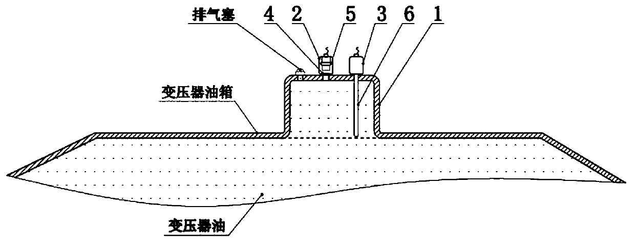
[0034] Embodiment 1: as figure 1As shown, in the part where the transformer fault gas floats upward or is easy to store, such as the upper cover of the oil tank, a gas collection chamber 1 is provided, and a gas composition detection device 2 and a gas volume detection device 3 are arranged on the upper part of the gas collection chamber. The gas component detection device 2 includes a detection element 5 and circuit elements for power supply and signal processing of the detection element. The detection element 5 can choose various types of combustible gas sensors, such as infrared type, semiconductor type, electrochemical type and catalytic combustion type. In order to realize the detection and prevent the insulating oil from polluting the detection element, the oil-gas isolation film 4 can be used to isolate the detection element from the insulating oil. The oil-gas isolation film 4 can be made of polytetrafluoroethylene material with good air permeability and isolation of i...

Embodiment 2

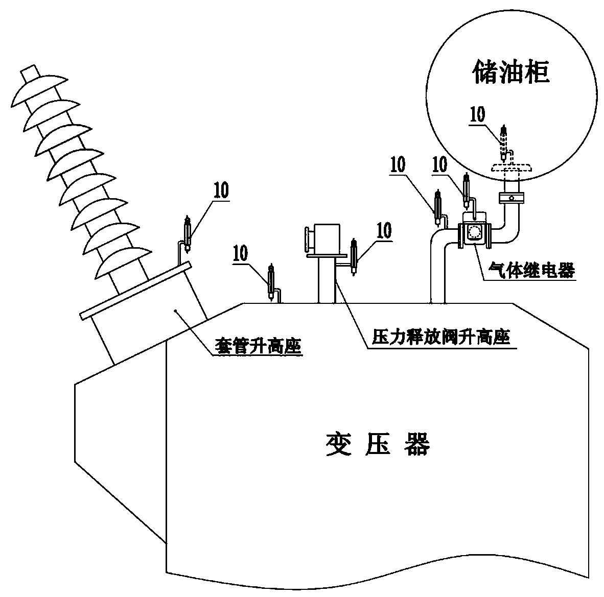
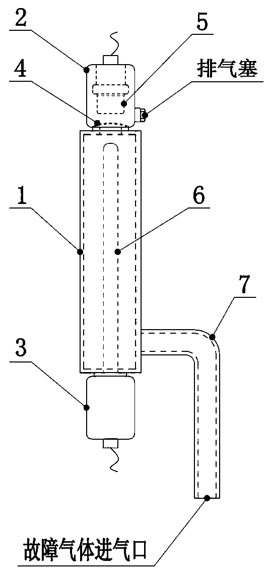
[0037] Embodiment 2: as figure 2 As shown, in the parts where the transformer fault gas floats upward or is easy to store, such as the upper cover of the oil tank, the rising seat of the bushing, the rising seat of the pressure release valve, the connection pipe of the oil tank leading to the gas relay, and the connection port of the gas relay and the oil storage tank At the high point where the gas is stored or passed, a detection component that communicates with the insulating oil inside the transformer is installed. Detection components such as image 3 As shown, it adopts a type that is easy to install, and is composed of a gas collection chamber 1, a gas component detection device 2 and a gas volume detection device 3. The air-collecting cavity is provided with a connecting port or connecting pipe 7 to communicate with the inside of the transformer. For the convenience of disassembly, a valve can be arranged at the connection with the transformer. The gas component det...

Embodiment 3

[0040] Embodiment 3: Gas relays are provided on the connecting pipes leading to the oil conservator from the upper part of the existing transformer oil tank, such as Figure 4 with Figure 5 As shown, the gas component detection device 2 and the gas quantity detection device 3 are arranged on the gas relay, communicated with the gas collection chamber of the gas relay, and the gas collection chamber of the gas relay is used as the gas collection chamber of the detection component. The gas component detection device 2 can be installed on the upper part of the gas collection chamber of the gas relay, guide the gas collected in the gas collection chamber to the gas detection element 5 through the air guide hole and the pipeline, and isolate the detection element 5 from the oil through the oil-gas separation film . The gas sampling hole on the upper part of the side wall of the gas relay can also be used to connect the tee, the upward pipeline is connected to the gas composition ...


PUM


Abstract

The invention relates to a transformer fault monitoring method. A gas collection cavity is arranged at a position where transformer fault gas floats upwards to pass or remain, a gas component detection device and a gas quantity detection device are connected to the gas collection cavity, and gas components and gas production speed in the gas collection cavity are directly detected. A transformer fault is found and a fault type is diagnosed by detecting a fault characteristic gas; and the fault severity is judged by detecting the gas production speed. When acetylene gas is detected and the gasproduction speed reaches a dangerous value, power-off protection is started. The method can quickly and accurately discover sudden faults of a transformer and timely diagnose whether chronic faults enter a dangerous period, effectively changes the current situation of serious lag of oil chromatography monitoring at present, and has important significance for improving the safety level of the transformer. The system is convenient to install and suitable for transformation of existing equipment and selection of new equipment.

Description

technical field [0001] The invention relates to a method for monitoring internal faults of electric power equipment. Specifically, a combustible gas component detection device is installed at the gas gathering part generated by a transformer fault to directly detect sensitive components and increments in the floating gas, and thereby discover faults and judge the degree of faults , and cut off the power in time. Background technique [0002] Transformer is the key equipment of power grid. When transformer fault occurs, combustible gas is accompanied by decomposition of insulating oil. Timely and effective detection of combustible gas generated by internal fault of transformer is of great significance to prevent the development and deterioration of transformer fault. [0003] Existing methods for detecting gas components inside transformers are mostly to collect oil samples of transformer insulating oil regularly or in real time, separate out dissolved gases in the oil, and a...

Claims


Application Information

Patent Timeline
IPC IPC(8): G01R31/00G01N21/25G01N33/00
CPCG01N21/25G01N33/0004G01R31/00
Inventor 孙艺夫郭思聪厍翠楼高素清刘妍
Owner 孙铭阳
Why Eureka
Try Eureka