
Tank container train loading and unloading arm
A tank container, loading and unloading arm technology, applied in packaging, distribution devices, transportation and packaging, etc., can solve problems such as pipeline slipping, difficulty in normal access to the discharge port, and difficulty in safe operation, etc., to improve efficiency, safety and reliability. performance, reduce construction costs and later operation and maintenance costs, and reduce the number of effects
- Summary
- Abstract
- Description
- Claims
- Application Information
AI Technical Summary
Problems solved by technology
Method used
Image

Examples
Embodiment Construction
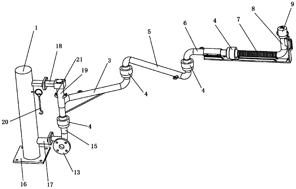
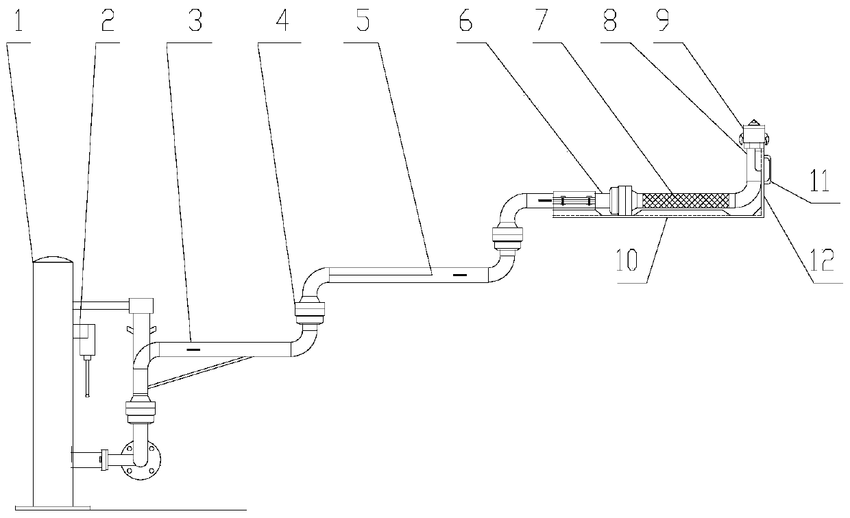
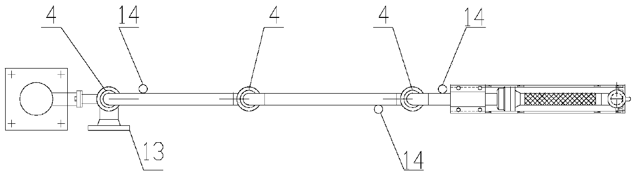
[0027] Such as Figure 1 to Figure 5 As shown, the present embodiment provides a tank container train loading and unloading arm, including a support mechanism, a lower arm tube 15, an inner arm tube 3, a middle arm tube 5, an outer arm tube 6, a metal hose 7, an upper arm tube 8 and a fast Parts such as joint 9.
[0028] The supporting mechanism is arranged on one side of the train track, and the lower arm pipe 15 is fixedly connected to the supporting mechanism. One end of the lower arm pipe 15 extends horizontally, and one end of the lower arm pipe 15 is provided with a pipe joint (flange 13 in this embodiment) One end of the lower arm pipe 15 can be connected to the oil pipeline through the flange 13, and the other end of the lower arm pipe 15 is bent upward to form a 90° elbow to connect with the inner arm pipe 3.
[0029] In this embodiment, the support mechanism is a supporting column 1, the bottom of which is fixed on the ground through an assembly plate 16, and a lowe...
PUM
 Abstract
Description
Claims
Application Information